background image

39

4. Adjustments

FinePix A400 Service Manual

4-5. Adjustment software installation

4-5-1. Various downloading software decompressions, preservation methods, and notes

The PC adjustment softwares are in a specified Web server,
and both of these are the compression of ZIP form files.
Therefore, after downloading these compression files from
the Web server, the decompression of the file is necessary.
In the decompression software, if the decompression of the
ZIP form can be done, any software is OK.
 (Please prepare each one for the decompression software.)
The decompression and the preservation method of the PC
adjustment software and the firmware are described
to the following.
* The PC adjustment soft decompression and preservation

method

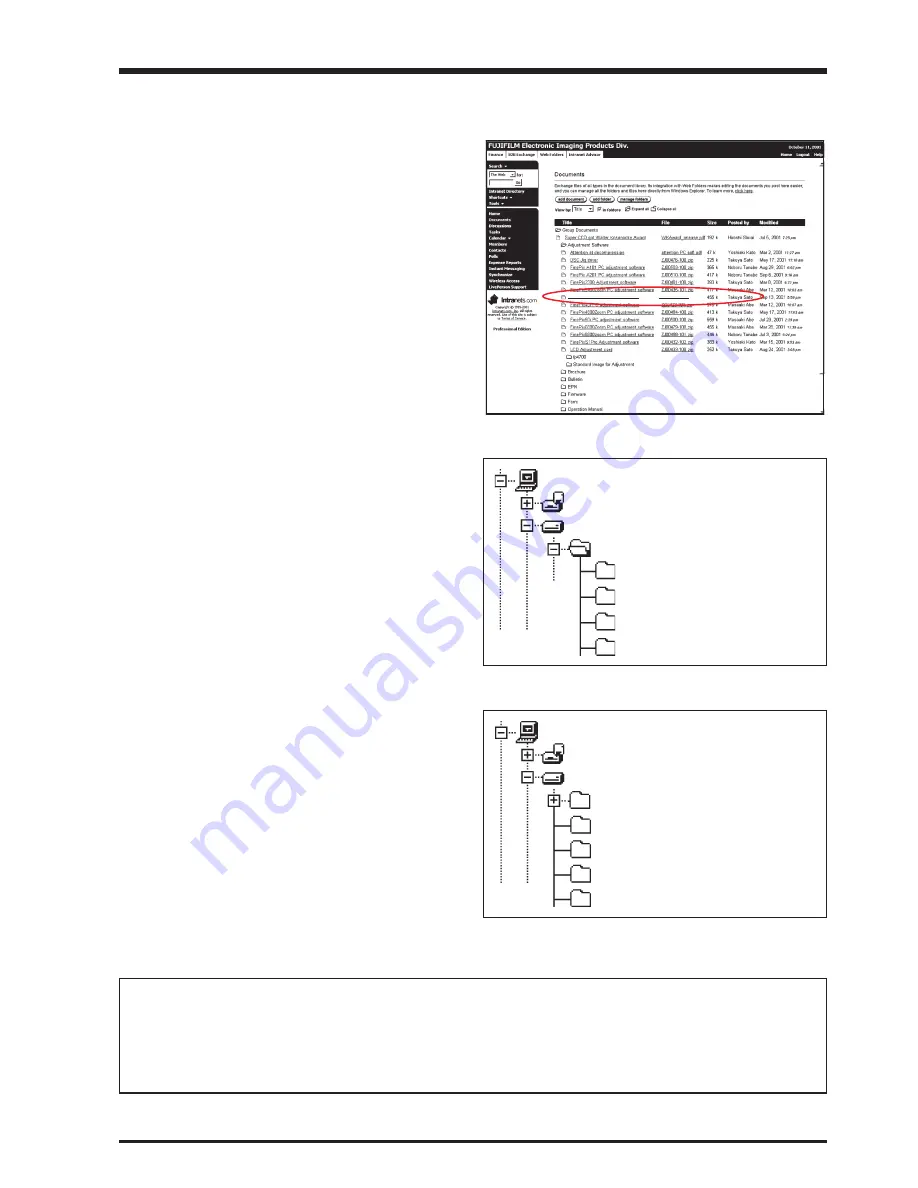
<Step1>
The sdjustment software is downloaded  from WEB, and
software is installed in the PC.
We have uploaded the 

“PC Adjustment Software

(ZJ00950-100.zip) for “FinePixA400_W”

 on our website:

(http://fujifilm-di.intranets.com/).

<Step2>

“ZJ00950-100”

 is a compression of “ZIP type” file.

The 

“A21_nose_cal”, “FinePixA400_W”, “sg3” and

“SU1830”

 folder can be done by extracting it by

“Compression software”.
Copy the “A21_nose_cal”, “FinePixA400_W”, “sg3” and
“SU1830” folder to the “C” drive on the Adjustment PC.

<Step3>
When all the folders have been copied to the C:drive,
double-click on [C:\ FinePixA400_W\ FFW.exe] to start the
adjustment software.

(Note)
* Specify the preservation drive for C drive if it

isdecompression software which can specify the
preservation drive.

* Similarly, defrost without making a new folder if it is

decompression software which can be defrosted without
making a new folder.

* Defrost simply if the decompression software which you

have cannot specify the drive specification and the folder
making.

<Fig. 4-5-3>

ZJ00950-100

My Computer

3.5inch FD(A:)
(C:)

A21_nose_cal
FinePixA400_W
sg3

<Fig. 4-5-1> Fujifilm-di.intranets Screen

FxA400 W PC Soft Ver.1.00

ZJ00950-100.zip

<Fig. 4-5-2>

ZJ00950-100

My Computer

3.5inch FD(A:)
(C:)

A21_nose_cal
FinePixA400_W
sg3
SU1830

SU1830

[Caution][Important]
(a) PC adjustment software can not start when there is folder of FinePixA400_W in folder named ZJ00950-100.

Please preserve the folder of A21_nose_cal, FinePixA400_W, sg3 and SU1830 right under C drive.

(b) Please do not change the foldername named FinePixA400_W.

PC adjustment software can not start when foldername is changed.

œ

œ

 Revised: 19. Apr. 2006

œ

œ

œ

Summary of Contents for FINEPIX A400

Page 1: ...T IF YOU USE PARTS NOT SPECIFIED IT MAY RESULT IN A FIRE AND AN ELECTRICAL SHOCK FUJI PHOTO FILM CO LTD Ref No ZM00625 104 Printed in Japan 2007 04 DIGITAL CAMERA FinePix A400 US CA EU EG EE AS CH Mod...

Page 2: ...red connections Check the entire board surface for solder splasher and bridges 2 Check the interboard wiring to ensure that no wires are pinched or contact high wattage resistors 3 Look for unauthoriz...

Page 3: ...s use a designated lead free solder bearing in mind the differing work practices for conventional solder eutectic and lead free solder Differences in the soldering work for lead free and eutectic sold...

Page 4: ...The correct bonding temperature refers not to the temperature of the heat source but to the bonding temperature that will give the best bond strength Precautions when soldering with lead free solder S...

Page 5: ...ol SnAgCu Solder wire thread Use the lead free solders specified below Solder type Sn96 5Ag3Cu0 5 Displayed symbol SnAgCu Wire diameter 0 6 0 8 or 1 0 mm Sample Flux Conventional flux can be used Sold...

Page 6: ...6 FinePix A400 Service Manual MEMO...

Page 7: ...37 4 3 Use Jig list 38 4 4 Calibration method of pattern box 38 4 5 Adjustment software installation 39 4 5 1 Various downloading software decompressions preservation methods and notes 39 4 5 2 Instal...

Page 8: ...Exposure compensation 2 EV to 2 EV in 1 3 EV step increments Shutter speed 2 sec to 1 1500 sec depend on Exposure mode Focus Mode Auto focus AF system TTL contrast type AF frame selection AF CENTER W...

Page 9: ...nd shot and the camera turned off and then on again once every 10 shots Note Because the number of available shots varies depending on the capacity of alkaline batteries or the level of charge in Ni M...

Page 10: ...98 SE Me 2000 Professional XP Mac OS 8 6 to 9 2 X 10 1 2 to 10 1 5 Standard number of available frames recording time per xD Picture Card internal memory The number of available frames recording time...

Page 11: ...frame rate is expressed as 10 fps For reference TV images are displayed at 30 fps NTSC JPEG Joint Photographic Experts Group A file format used for compressing and saving color images The higher the...

Page 12: ...icture Card slot Battery compartment Playback button Viewfinder lamp Viewfinder LCD monitor Tripod mount POWER button Flash Viewfinder window Macro button Flash button VIDEO OUT Video output socket US...

Page 13: ...assembly FinePix A400 Service Manual 2 Disassembly 2 1 Names of internal Components LCD LENS CONST F CASE ASSY BATTERY HOLDER ASSY BUZZER FLASH CASE ASSY FRAME REAR CASE LEAD E CAP SUB PWB ASSY MAIN P...

Page 14: ...in the direction of the arrow 5 Peel off the FLASH SHEET and discharge the main capacitor Take care not to touch the SUB PWB ASSY before discharging the capacitor 6 Unlock the CN501 connector 7 Remov...

Page 15: ...he 6 screws M1 4 x 3 0 2 Remove the FRAME in the direction of the arrow 3 Remove the LCD in the direction of the arrow 4 Remove the POWER BUTTON in the direction of the arrow 5 Remove the RELEASE HOLD...

Page 16: ...f the arrow 4 Detach the FPC CCD from the connector in the direction of the arrow 5 Remove the soldering at 2 points 6 Remove the soldering at 2 points and disconnect the lead wires 7 Remove the 3 scr...

Page 17: ...S CONST in the direction of the arrow 2 Remove the F INNER PSP in the direction of the arrow 3 Remove the BUZZER in the direction of the arrow 4 Remove the 2 screws M1 7 x 4 0 5 Remove the BATTERY HOL...

Page 18: ...SH SHEET 4 Remove the soldering at 4 points 5 Remove the main capacitor in the direction of the arrow 6 Remove the soldering for T952 7 Remove the screw M1 7 x 4 0 8 Remove the SUB PWB ASSY in the dir...

Page 19: ...cteristics of variable resistors and semi fixed resistors are not displayed 3 2 Basic Block Names and Functions Part name Block name Function LENS CONST CCD BLOCK CCD output MAIN PWB ASSY CAMERA BLOCK...

Page 20: ...O BUFFER The image data for each frame is temporarily stored in the XCS2R_IC SDRAM At the same time the AE for AUTO is calculated using the 10 bit image data input to XCS2R_IC and the data required fo...

Page 21: ...N O _ K L C D C C LENS Barrier S N E L M O O Z x 3 s p e t S 2 S I R I e l b a i r a V E L E T E D I W O LPF D C C A H C 0 3 9 3 S M h c n i 5 2 1 s l e x i p n o l l i m 0 4 G R D F O S A I B F 5 2 1...

Page 22: ...22 3 Schematics FinePix A400 Service Manual 3 5 Overall connection Diagram...

Page 23: ...23 3 Schematics FinePix A400 Service Manual 3 6 Circuit Diagrams 3 6 1 CAMERA BLOCK...

Page 24: ...24 3 Schematics FinePix A400 Service Manual 3 6 2 DCDC BLOCK...

Page 25: ...25 3 Schematics FinePix A400 Service Manual 3 6 3 MOTOR BLOCK...

Page 26: ...26 3 Schematics FinePix A400 Service Manual 3 6 4 PROCESS BLOCK...

Page 27: ...27 3 Schematics FinePix A400 Service Manual 3 6 5 SUB BLOCK z Revised 22 Sep 2006 z...

Page 28: ...28 3 Schematics FinePix A400 Service Manual MEMO...

Page 29: ...29 3 Schematics FinePix A400 Service Manual 3 6 6 KEY BLOCK...

Page 30: ...30 3 Schematics FinePix A400 Service Manual 3 6 7 LCD BLOCK...

Page 31: ...31 3 Schematics FinePix A400 Service Manual 3 6 8 CCD FPC BLOCK 3 6 9 VIDEO BLOCK...

Page 32: ...32 3 Schematics FinePix A400 Service Manual 3 6 10 MEDIA BLOCK 3 6 11 STRB BLOCK...

Page 33: ...33 3 Schematics FinePix A400 Service Manual 3 7 Mounted Parts Diagrams 3 7 1 CCD FPC ASSY...

Page 34: ...34 3 Schematics FinePix A400 Service Manual 3 7 2 MAIN PWB ASSY SIDE A...

Page 35: ...35 3 Schematics FinePix A400 Service Manual SIDE B...

Page 36: ...36 3 Schematics FinePix A400 Service Manual 3 7 3 SUB PWB ASSY SIDE A SIDE B Revised 17 Feb 2006...

Page 37: ...alent Flash meter Used for function checks 4 2 Measuring Instruments Used Replacing parts Adjustment item CCD PWB LENS CONST LENS UNIT MAIN PWB 0 Flash memory reset 1 CCD Data Input adjustment 2 Camer...

Page 38: ...ZJ00254 100 Gray Chart Reflective type Flash adjustmen Common with the MX700 MX500 FZ06231 100 USB cable General adjustment Common with the FinePiX F10 1 ZJ00950 100 FxA400 W PC Soft Ver 1 00 PC adju...

Page 39: ...done by extracting it by Compression software Copy the A21_nose_cal FinePixA400_W sg3 and SU1830 folder to the C drive on the Adjustment PC Step3 When all the folders have been copied to the C drive...

Page 40: ...ter it is not necessary to install it The procedure is given below Step 1 DSC jig driver ZJ00684 100 ZIP is downloaded from Web server http fujifilm di intranets com Step 2 Defrost the downloaded comp...

Page 41: ...is rewritten the adjustment software will not startup Step 1 Double click on the FFW exe execute file of the adjustment software to open the FinePix A400_W Adjustment Software Startup screen Fig 4 6...

Page 42: ...If Disable OKNG display on the PC screen Fig 4 6 4 is set to OFF the PC screen displays OK if adjustment is OK and NG if adjustment is NG either setting is OK Step 5 Select the Hardware tab 1 in Fig...

Page 43: ...or Auto Adjust in user program Help Help Basic software help FF help User program help Focus Not used with this adjustment software Version Version information for basic software Table FFW exe Command...

Page 44: ...software 4 Proceed with adjustment after reading the cautions here and the relevant cautions noted in the Service Manual Press the Enter key to proceed to the Jig Mode Setup screen Fig 4 7 2 FinePix A...

Page 45: ...3 0 0 1V by using FxA500 A400 Battery jig 2 When executing the other adjustment supply power 3 0 0 1V by using Power cable jig 1 Open the Battery cover 2 Connect the USB cable 3 Supply 3 0V 0 1V to t...

Page 46: ...ion number of the adjustment software 2 After running firmware download other adjustments may be required depending on the content of the download software In such cases the items to be adjusted and t...

Page 47: ...l completion of the adjustments In some cases the camera may be completely disabled If this occurs set the camera to jig mode again and then reset the flash memory Step 1 In the adjustment item select...

Page 48: ...N PWB ASSY has not been replaced all the adjusted data reverts to the default settings In this event adjust all the settings Excludes firmware downloading Enter RESET from the PC keyboard R E S E T In...

Page 49: ...settings to ensure that it is displayed 2 In addition to numbers letters are also used in the CCD serial No The data file name is instructed in the same manner in this case 3 Ensure that the CCD seria...

Page 50: ...data input CCD data input Preparations 1 Adjust the color temperature of the pattern box PTB450 to 6100 50K 2 Adjust the luminance of the pattern box PTB450 to 160 5cd m2 3 Fix the camera on a tripod...

Page 51: ...ttern box 2 The LB140 filter is not placed in front of the lens When preparations are complete press the Enter key LB140 filter 5mm or 30mm or less less Center Center Pattern box PTB450 CAMERA Setup f...

Page 52: ...ra Adjustment Preparation screen appears Step 2 Run the adjustment in accordance with the instructions on the screen Note An error will occur during Camera adjustment and adjustment cannot be complete...

Page 53: ...tup for Camera Adjustment Fig 4 10 2 Squeezing sensitivity decrease rate adjustment 1 Set the distance between the camera and pattern box 2 Place the LB140 filter in front of the lens When preparation...

Page 54: ...Pattern box PTB450 CAMERA Setup for Camera Adjustment Fig 4 10 5 OFD sensitivity adjustment 1 Set the distance between the camera and pattern box 2 The LB140 filter is not placed in front of the lens...

Page 55: ...plete press the Enter key LB140 filter 5mm or 30mm or less less Center Center Pattern box PTB450 CAMERA Setup for Camera Adjustment Fig 4 10 6 Camera adjustment is completed Press the Enter key to ret...

Page 56: ...ight source Ensure that the brightness at the surface of the AF chart is between 9 0 and 11 5EV 3 Place the conversion lens concentric with the camera lens Step 1 Select F6 AF adjustment on the Adjust...

Page 57: ...14 5mm from the lens front of the camera 2 Place the conversion lens at a distance of 14 2mm from the lens front of the camera 3 Adjust the position of the camera so that the center of the AF chart is...

Page 58: ...58 4 Adjustments FinePix A400 Service Manual Fig 4 11 4 Step 5 The AF adjustment is completed Press the Enter key to return to the Adjustment Items Select Screen...

Page 59: ...ly affected by external light ensure that the vicinity of the gray chart is very dark 2 Ensure that distance is measured from the front of the camera during flash adjustment 3 When adjusting the flash...

Page 60: ...D monitor When preparations 1 and 2 are complete press the Enter key 1000 10mm Center CAMERA Setup for Flash Adjustment Fig 4 12 2 Step 3 Write the adjustment data to the flash ROM when adjustment has...

Page 61: ...adjust the stabilized power supply to ensure that the voltage is not reduced excessively from the measured point The adjustment software may produce an error if communication between the adjustment so...

Page 62: ...era are connected If not return to the Jig Mode Setup screen and connect the FxA500 A400 Battery jig and the camera 2 Supply power 3 00V 0 1V to the camera from the FxA500 A400 Battery jig When prepar...

Page 63: ...upply 3 00V 0 1V When preparations are complete press the Enter key Fig 4 13 3 Battery voltage adjustment 1 Supply 2 20V 0 02V 0 00V When preparations are complete press the Enter key Result 2 Supply...

Page 64: ...64 4 Adjustments FinePix A400 Service Manual Fig 4 13 5 The Battery voltage adjustment is completed Press the Enter key to return to the Adjustment Item selection Screen Step 7...

Page 65: ...s signal Y or color signal C does not appear in the WAVE No 0 window during adjustments check the connections of the video adjustment jig Step 1 Select F11 Video adjustment on the Adjustment Items Sel...

Page 66: ...adjustment VIDEO Adjustment Preparations 1 Connect the camera and video adj jig with the video cable 2 Confirm Video jig is connected with the video cable When preparations are complete press the Ent...

Page 67: ...irmware Download on the Adjustment Items Select screen The Download Complete screen appears if download is successful USB DC JACK FinePix A500 A400 PC for adjustment and check Regulated power supply D...

Page 68: ...Power cable jig from the camera 2 Turn off power switch 3 Reconnect Power cable jig 4 Switch camera power ON while pressing the shutter button 5 Press the Enter key after green LED lights on The syst...

Page 69: ...ue throughout the world For this reason each device has a unique ID as determined by the USB standard If multiple devices with the same USB ID are connected to a single PC the PC will be unable to ide...

Page 70: ...to Z Fig 4 16 2 End Setting The End settings consist of the destination setting the USB_ID write and product mode settings Mass Storage recognition Press the Enter key Fig 4 16 1 Step 1 Select F12 End...

Page 71: ...US CA model Press the Enter key Fig 4 16 3 Repair site ID input menu The repair site is selected from an undermentioned list A SAPPORO SS M BRITAIN B SENDAI SS N GERMANY C TOKYO SS O FRANCE D NAGOYA S...

Page 72: ...tment End screen appears Step 7 USB ID Selected U S A Press the Enter key Fig 4 16 5 Fig 4 16 6 FinePix A400 Adjustment completed 1 Remove USB cable from the camera 2 Press the Enter key The adjustmen...

Page 73: ...use able to measure 1mA or less FxA500 A400 Battery jig Common with adjustment JIG ZJ00956 100 xD Picture card For general use Macro Chart Resolution confirmation ZJ00525 100 TV Monitor TV monitor min...

Page 74: ...y status 6 Check for blemishes in the CCD live image 1 Zoom drive noise 2 Check the finder 3 Zoom operation T W 1 Apply a shock to the camera using the shock jig 1 Check for damage to the outer casing...

Page 75: ...e 1 Select the Movie shooting mode 2 Press S1 S2 and then release S2 S1 3 After 5 seconds press and then release S1 1 Set the camera to Playback mode 2 Press the 4 way button down to play back the mov...

Page 76: ...u and then press the OK button 2 Press the OK button again 2 Check that the position ofthe bright spot is within a10 circle with a centerthat is X 1 and Y 3 from the center of thevectorscope see figur...

Page 77: ...set to red eye reduction mode and then select AUTO mode Check that there are no noticeable dust flecks or stains bright spots smears flashing points etc on the screen 2 3 0 0 1 V 4 2 20 0 05 V Check t...

Page 78: ...hat the lensbarrier and flash areclosed 5 Check that the internal memory is formatted 1 New The default SETUP frame No setting is Continuous but to clear the number of frames in the frame number memor...

Page 79: ...100 200 A106 FZ06533 100 HAND STRAP A107 FZ06091 100 AV CABLE A108 FZ06230 101 USB CABLE W A109 FZ06487 100 ALKALINE BATTERY A110 AZF0000 101 LDPE BAG NO 10 A111 FZ06521 100 CD ROM A112 BB18002 100 C...

Page 80: ...G 100 200 A106 FZ06533 100 HAND STRAP A107 FZ06091 100 AV CABLE A108 FZ06230 101 USB CABLE W A109 FZ06487 100 ALKALINE BATTERY A110 AZF0000 101 LDPE BAG NO 10 A111 FZ06521 100 CD ROM A112 BB18002 100...

Page 81: ...200 A106 FZ06533 100 HAND STRAP A107 FZ06091 100 AV CABLE A108 FZ06230 101 USB CABLE W A109 FZ06487 100 ALKALINE BATTERY A110 AZF0000 101 LDPE BAG NO 10 A111 FZ06521 100 CD ROM A112 BB18002 100 CERTIF...

Page 82: ...19 100 HDPE BAG 100 200 A106 FZ06533 100 HAND STRAP A107 FZ06091 100 AV CABLE A108 FZ06230 101 USB CABLE W A109 FZ06487 100 ALKALINE BATTERY A110 AZF0000 101 LDPE BAG NO 10 A111 FZ06521 100 CD ROM A11...

Page 83: ...EL BLANK A105 BB18019 100 HDPE BAG 100 200 A106 FZ06533 100 HAND STRAP A107 FZ06091 100 AV CABLE A108 FZ06230 101 USB CABLE W A109 FZ06487 100 ALKALINE BATTERY A110 AZF0000 101 LDPE BAG NO 10 A111 FZ0...

Page 84: ...EL BLANK A105 BB18019 100 HDPE BAG 100 200 A106 FZ06533 100 HAND STRAP A107 FZ06091 100 AV CABLE A108 FZ06230 101 USB CABLE W A109 FZ06487 100 ALKALINE BATTERY A110 AZF0000 101 LDPE BAG NO 10 A111 FZ0...

Page 85: ...551 100 PARTITION PAD A103 FZ06459 100 SHEET MOLD FC A104 BB12943 100 BAR CODE LABEL BLANK A105 BB18019 100 HDPE BAG 100 200 A106 FZ06533 100 HAND STRAP A107 FZ06091 100 AV CABLE A108 FZ06230 101 USB...

Page 86: ...AR CODE LABEL BLANK A105 BB18019 100 HDPE BAG 100 200 A106 FZ06533 100 HAND STRAP A107 FZ06091 100 AV CABLE A108 FZ06230 101 USB CABLE W A109 FZ06487 100 ALKALINE BATTERY A110 AZF0000 101 LDPE BAG NO...

Page 87: ...R ASSY M220 BB19252 100 BATTERY HOLDER B C C A B A D M231 M230 M232 M229 M238 M234 M235 M227 M237 M236 M239 M233 K TAPE M205 M237 M215 M204 M216 M210 M211 M209 M214 M213 M212 M208 M206 M218 M228 M207...

Page 88: ...BB19252 100 BATTERY HOLDER B C C A B A D M231 M230 M232 M229 M238 M234 M235 M227 M237 M236 M239 M233 K TAPE M205 M237 M215 M204 M216 M210 M211 M209 M214 M213 M212 M208 M206 M218 M228 M207 M221 M238 M...

Page 89: ...ER ASSY M220 BB19252 100 BATTERY HOLDER B C C A B A D M231 M230 M232 M229 M238 M234 M235 M227 M237 M236 M239 M233 K TAPE M205 M237 M215 M204 M216 M210 M211 M209 M214 M213 M212 M208 M206 M218 M228 M207...

Page 90: ...19252 100 BATTERY HOLDER Revised 17 Feb 2006 B C C A B A D M231 M230 M232 M229 M238 M234 M235 M227 M237 M236 M239 M233 K TAPE M205 M237 M215 M204 M216 M210 M211 M209 M214 M213 M212 M208 M206 M218 M228...

Page 91: ...HT GUIDE M306 BB19262 100 RELEASE HOLDER M307 BB19260 100 RELEASE CSP M308 BB19259 100 RELEASE BUTTON M309 BB19261 100 POWER BUTTON M310 FZ06495 100 LCD M311 BB19330 100 GASKET LCD M312 BB19266 100 FR...

Page 92: ...0351 CONNECTOR CJ 35P FN 0 3MM NH CN601 FGY099 0201 CONNECTOR CJ 20P B 1MM NN CN601 FGY102 0201 CONNECTOR J 20P B 1MM NN CN701 FGB161 0221 CONNECTOR CJ 22P FN 0 5MM NH CN901 FGB161 0181 CONNECTOR CJ 1...

Page 93: ...The power supply switch is turned on while pressing the shutter button 3 The SETUP display is selected and changes to a DATE TIME set mode 4 The DATE TIME setting is matched as follows Fig 7 1 2040 2...

Page 94: ...e Title Details Other 2006 011 17 Feb 2006 Service manual revision Revised page P34 P58 P65 to P66 P84 to P86 and P88 to P89 2006 039 19 Apr 2006 Service manual revision Revised page P35 to P37 and P4...

Page 95: ...26 30 Nishiazabu 2 chome Minato ku Tokyo 106 8620 Japan FUJI PHOTO FILM CO LTD...

Reviews: