


© 2015 Flanders Scientific, Inc.
27
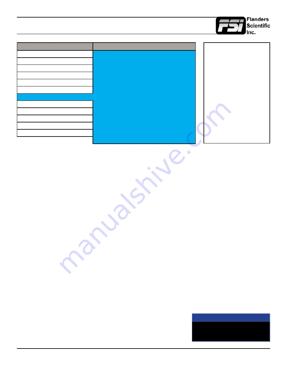
Alarm Menu
Main Menu
Alarm
Function
Alarm
Off
Scopes & Audio Meters
Visual Alarm
Off
Video
Remote Alarm Monitoring
Off
Audio
IRE Trigger Level
100 IRE
Marker
Audio Trigger Time
5s
System
UMD Display
UMD
Alarm
UMD Color
White
OSD
UMD Position
Bottom
GPI
Audio Meter
Vertical
Display Alignment
Select Alarm Area
System Status
RS422 Address
1
Support
Baud Rate
9600
Parity
None
The monitor’s built in Alarm system allows for simplified QC monitoring of signals with minimal overlap of active video.
The alarm monitoring system allows you to specify alarm parameters that will trigger onscreen and/or remotely monitored
warnings when a specified condition is met. This feature provides an unobtrusive QC viewing mode compared to having
onscreen scopes active at all times. Please note the alarm monitoring capabilities are limited by the processing power of
the monitor. The signal will be sampled at a variable rate depending on other processing loads placed on the monitor. With
minimal additional processing demands the fastest sample rate is approximately every 2 to 3 frames. It is therefore possible
that an alarm event occurring for only 1 or 2 frames may be missed by the alarm monitoring system. The alarm monitoring
system is a useful tool for quick analysis of content to make sure no serious errors exist, but it should not be used as
substitute for standalone legalizers and signal level monitoring systems in ultra-critical level monitoring applications.
Alarm
Selects the type of alarm events that will be monitored. This selection
only
affects onscreen (visual) alarms and does not
change what alarm events can be monitored through the remote control alarm monitoring software.
Safety Alarm:
Will trigger an alarm if a loss of signal is detected, a full black field is detected, a full blue field is detected,
and/or embedded audio goes mute for the amount of time specified in the Audio Trigger Time setting. The audio mute
alarm will only trigger if audio is being embedded into the signal and is mute for the specified amount of time, there will
be no audio mute warning if audio is not being embedded into the SDI signal.
Safety Video Alarm: Same as Safety Alarm minus audio alarms.
IRE Alarm:
Will trigger an alarm if the IRE level specified in the IRE Trigger Level setting is exceeded.
RGB Alarm:
Will trigger an alarm if any RGB Levels exceed 100 IRE.
IRE & RGB Alarm:
Combines IRE and RGB Alarms and will trigger an alarm if either or both exceed their set parameters.
All Alarms:
Will trigger an alarm if any alarm condition is met (Loss of Signal, Black Field, Blue Field, Audio Mute, IRE
threshold exceeded, RGB levels over 100 IRE).
Visual Alarm
When set to ON a small box will appear on the monitor’s screen whenever the
alarm condition set in the Alarm menu selection explained above is triggered.
NOTE: Onscreen Alarms are
processing power intensive.
When active the monitor may
respond more slowly to user
input via buttons/remote control
if a large number of successive
alarm events are occurring.
Switching to an unused input with
no video will allow the monitor
to respond quickly to user input
should the operator simply want
to turn Alarm monitoring off in
scenarios where monitor menu
response is slowed by such
successive alarm events.
Alarm
IRE


