FSI AM250 User Manual Download Page 16

© 2015 Flanders Scientific, Inc.

16

Return to Table of Contents

Function Menu

AFD (Active Format Description)


Anamorphic De-Squeeze

This feature gives you the ability to de-squeeze HD signals coming from cameras utilizing anamorphic lenses that may not 

have a built in de-squeeze feature of their own. This can be particularly useful in applications outside of post production, 

especially onset monitoring, where de-squeezing such signals in real-time may otherwise not be possible. The de-squeeze 

modes available are 1.3, 2.0, and 2.0mag. This feature is in addition to, and not a substitute for, the SD Aspect Ratio function. 

To use this feature set Anamorphic DeSqueeze to a function button, which will allow you to toggle the de-squeeze on and 

off. To set the desqueeze ratio/magnification go to the Video Menu and select your desired Anamorphic De-Squeeze mode. 

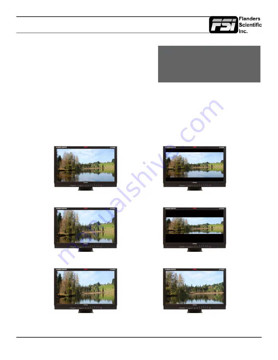
Anamorphic De-Squeeze Modes


Activating  this  function  will  enable  an  Active  Format  Description 

reader  on  the  monitor  that  will  provide  both  a  text  readout  of AFD 

data  and  display  corresponding  markers  onscreen  indicating 

the  portions  of  the  image  described  by  the  AFD  code.  If  no  AFD 

data  is  present  while  this  feature  is  active  the  monitor  will  show  

AFD: NONE in its AFD readout window.

1.3x Anamorphic Original

1.3x Anamorphic De-Squeeze

2.0x Anamorphic Original

2.0x Anamorphic De-Squeeze

2.0x Anamorphic Original

2.0x mag Anamorphic De-Squeeze

AFD: 0x0d

code frame 16:9

active image 4:3

image position horizontal center

with alternative 14:9 center

Summary of Contents for AM250

Page 1: ...8 835 4934 Fax 1 678 804 1882 E Mail Support FlandersScientific com www FlandersScientific com AM Series AM210 AM250 AM420 AM550 This manual is based on firmware version 1 0 00 1976 If you have an older or newer firmware version some of the functions mentioned in this manual may not be present or may operate differently ...

Page 2: ...ions 3 4 Parts Their Functions 5 6 Menu Navigation System Status 7 Function Menu 8 17 Marker Menu 18 Video Menu 19 20 Scopes VU Meters Menu 21 23 System Menu 24 26 Alarm Menu 27 29 OSD Menu 30 GPI Menu 31 Audio Menu 32 Display Alignment Menu 33 Display Alignment Menu Custom Calibration LUTs 34 35 ...

Page 3: ...aged When any liquid is spilled on or in the product When the product has been exposed to rain or water When the product does not operate properly as described in the instruction manual When the product has been dropped or damaged If the product requires replacement parts make sure that the service person uses replacement parts specified by the manufacturer or those equivalent parts having the sam...

Page 4: ...lt in serious obstruction of ventilation areas If using in enclosed space make sure to provide proper ventilation to maintain allowable operating temperature range The panel used in this product contains glass and can cause serious injury if broken If the unit is dropped or otherwise damaged take care to avoid possible injury by glass shards Keep this product away from heat generating sources such...

Page 5: ...oggle On Screen Menu LEFT Used to navigate On Screen Menu UP Used to navigate On Screen Menu DOWN Used to navigate On Screen Menu RIGHT ENTER Used to navigate On Screen Menu and to confirm selections within the On Screen Menu PHASE A1 Used to adjust phase Press the Phase key and use the Up and Down arrows to adjust Hue is locked by default on SDI but can be unlocked by the SDI Hue Adjustment optio...

Page 6: ...u Video In Out Composite Video Input Loop Through Component In Out Component Video SD HD autosensing Input Loop Through Supports both YPbPr RGB signals Ext Sync In Out External Reference Synchronization Interface SDI In 1 SDI In 2 Two Autosensing Autoswitching Multi Format 3G HD SD SDI Inputs SDI Out 1 Out 2 Two looped 3G HD SD SDI Switched Outputs Audio In Out Analog Stereo Mini phono Audio Input...

Page 7: ...nu or sub menu press the LEFT button To exit the menu simply press the MENU button System Status The System Status category does not contain any configurable settings but does provide important information regarding your monitor s serial number firmware version current configuration Main Menu System Status Function Input DVI D Scopes Audio Meters Input Mode 1080p 60hz Video Volume 16 Audio Contras...

Page 8: ...antly toggle between various types of Scope and or Audio Level Meter configurations Please note that if you have set both Scopes Windows to the Off position in the Scopes Audio Meters menu nothing will appear on screen when you toggle this function see Scopes Audio Meters Menu section of this manual for more details Cross Hatch The Cross Hatch function toggles on off the onscreen display of a grap...

Page 9: ...apping function With both Pixel to Pixel mapping and Overscan selected the area outside of the active scan will simply be blacked out but the active video will not be scaled outside of the 1 1 pixel scan With Pixel to Pixel mapping off and overscan on the active scan area will be scaled full screen To view all active lines in Pixel to Pixel mapping mode make sure to turn Overscan off Pixel to Pixe...

Page 10: ...larly on all native 1920x1080 or 1920x1200 resolution monitors this mode will allow you to view any portion of an incoming 2K source in an unscaled 1 1 onscreen representation 2 1 Pixel Mapping SD sources only Every individual pixel of the incoming source is represented by four pixels onscreen This scaling algorithm is simple and allows for a largely artifact free double size version of the 1 1 Pi...

Page 11: ...ixel Zoom feature entirely simply press the function button assigned to this feature once more The Pixel Zoom function allows for an essentially artifact free high quality zoom on any portion of an HD signal LUM Coloring The A1 and A2 buttons will adjust the lower limit of the upper color coded region The A3 and A4 buttons will adjust the upper limit of the upper color coded region These color cod...

Page 12: ...0 255 for 8 bit and 0 1023 for 10 bit B Blue level as an absolute value between 0 255 for 8 bit and 0 1023 for 10 bit You can also press the A3 button to set a reference position onscreen Once your reference position is set it will be indicated on screen by a separate crosshair and you will be able to move the active crosshair to obtain a real time readout of your current and reference positions a...

Page 13: ...ce expressed as dE2000 value You can press the Ref A3 button to define a reference position on screen Once your reference position is set it will be indicated on screen by a separate crosshair and you will be able to move the active crosshair to obtain a real time readout of your current and reference positions as well as a separate readout of the precise difference between current and reference l...

Page 14: ... Level B Variable Wipe function off to remove the guide line between the two signals Still Frame This function allows you to freeze a video source at anytime To unfreeze simply press the function key assigned to Still Frame a second time Zoom This function zooms in on the incoming source until the entire screen is filled This is strictly a zooming function and does not alter the native aspect rati...

Page 15: ...ge window red background and DSLR in 1080i Preview with DSLR Zoom feature Off DSLR in 1080i Preview with DSLR Zoom Feature On DSLR in 480p Record Mode with DSLR Zoom feature off DSLR in 480p Record Mode with DSLR Zoom feature On enhanced timecode display large timecode overlay window Please note that as with the standard Alarm Monitoring feature the monitor may respond slowly to user toggles input...

Page 16: ... DeSqueeze to a function button which will allow you to toggle the de squeeze on and off To set the desqueeze ratio magnification go to the Video Menu and select your desired Anamorphic De Squeeze mode Anamorphic De Squeeze Modes Activating this function will enable an Active Format Description reader on the monitor that will provide both a text readout of AFD data and display corresponding marker...

Page 17: ...should only be used to offer on set viewers a rough normilization of the footage to give them an idea of what the content might look like as a starting point in post production In other words it provides you with a helpful tool to show on set viewers something that does not look flat These modes are not a replacement for full 3D LUT transforms and not a substitution for proper color correction in ...

Page 18: ... to Normal The Safety Marker may be displayed relative to the incoming source or the Area Marker by toggling the Safety in Area option on the Marker Menu Marker BG The Marker Background setting can be used to toggle how the area that lies outside of the Area Marker or Safety Marker boundaries is represented You can select from Normal Transparent or Solid Center Marker Toggles whether the center ma...

Page 19: ...og modes there is both a Standard and Full selection The Standard selection is suitable for most applications but does clip highlights to allow for a brighter overall image The Full mode is best used for scenes with extremely wide latitude or scenes that are just very bright overall Full mode preserves the entire native latitude of the signal nothing is clipped but this can result in a rather dark...

Page 20: ...een Interlaced or Progressive to instruct the monitor how to handle and show PsF content on screen Please note that when to set Progressive this will add processing delay even if the signal is not PsF Set to interlaced for lowest possible processing delay Please note that some features like Horizontal Audio Level Meters are NOT compatible with Show PsF as set to Progressive Composite Setup Allows ...

Page 21: ...YCbCr Overlay Column YRGB Peak Histogram Color Histogram RGB Histogram Audio Phase and Vertical Audio Level Meter Please note that displaying two Scope Windows at the same time will cause the Scopes to update more slowly than displaying just one Scope Window To display just one scope Window select OFF in the secondary window selection An additional audio level meter mode called horizontal audio le...

Page 22: ... organized in groups the channels will be arranged with all channels of an Audio Group displayed on the same side of the screen together Audio Display Channels Allows you to select the Audio Level Meters Channels that will be shown on the Vertical or Horizontal Audio Level Meters Select from Channels 1 2 1 8 9 16 or 1 16 Permitted Max Level Allows you to specify the Max Audio Level for your onscre...

Page 23: ...nc 23 Return to Table of Contents Scopes Audio Meters Luminance Vector Scope Hue Vector RGB GBR Parade Color Histogram YCbCr RGB Histogram Column YRGB Peak Histogram YCbCr Overlay RGB Overlay Audio Phase Meter Audio Level Meters ...

Page 24: ...tween Full RGB 0 255 Limited RGB 16 235 or YCbCr modes Component Input Component Pixel Format Use Component Pixel Format to toggle the Analog Component Video Inputs between YPbPr or RGB mode on all models 3G Level B 3Gbps SDI Level B Split Screen Vert or Horiz Picture in Picture Picture by Picture Link B Full Screen Link A Full Screen Link A Link B Overlay Mode 4 4 4 or 1080p50 60 4 4 4 SMPTE 425M...

Page 25: ...g Modes In addition to this Line by Line mode all FSI monitors with 3Gbps SDI inputs will have the following diagnostic modes for monitoring 3D signals without glasses 3D Checkerboard Checkerboard display of both signals with alternating blocks shown from Link A and Link B of the multiplexed 3Gbps SDI signal The checkerboard size is adjustable using the Checkerboard Size menu option 3D Disparity T...

Page 26: ...ightness setting Luminance Interval The luminance interval is a power saving feature It allows you to specify the amount of time without an active signal being shown on the monitor that should be allowed to expire before the monitor s backlight if applicable is turned off to reduce the power consumption of the unit When placed in the On position the monitor will not enter the power saving mode and...

Page 27: ...events that will be monitored This selection only affects onscreen visual alarms and does not change what alarm events can be monitored through the remote control alarm monitoring software Safety Alarm Will trigger an alarm if a loss of signal is detected a full black field is detected a full blue field is detected and or embedded audio goes mute for the amount of time specified in the Audio Trigg...

Page 28: ...screen similar to the custom graticules feature on the marker menu to define the onscreen area that will be monitored Once your desired area has been set simply use the left button to back out of the Select Alarm Area function The default alarm monitoring area is the whole screen but this function allows users to specify smaller regions if only a portion of the screen area needs to be monitored UM...

Page 29: ...olor White OSD UMD Position Bottom GPI Audio Meter Vertical Display Alignment Select Alarm Area System Status RS422 Address 1 Support Baud Rate 9600 Parity None Baud Rate Sets the RS422 baud rate This should be left at the default 9600 value unless otherwise specified by Flanders Scientific s support department Parity Sets Parity for RS422 communication This should be left at the default None posi...

Page 30: ...r Top Right Status Pos Changes position of onscreen status display window Select from Top Left Top Right Bottom Left Bottom Right or Center Rotary Pos Changes position of onscreen window indicating status of Volume Contrast Phase Brightness Chroma etc during adjustment Select from Top Center or Bottom Source ID Allows you toggle source ID function on off The Source ID function can be used to set a...

Page 31: ...ocated on the back of the monitor the pins are arranged 1 through 8 from right to left This GPI interface is a contact closure based system and PIN 5 is always the ground The GPI numbering on the GPI menu corresponds to the physical Pin assignments as follows Menu RJ 45 Pin GPI 1 Pin 1 GPI 2 Pin 2 GPI 3 Pin 3 GPI 4 Pin 4 GPI 5 Pin 6 GPI 6 Pin 7 GPI 7 Pin 8 To prevent conflicts between menu toggles...

Page 32: ...re will be the stereo pair shown when the Audio Phase Meter is activated on the SDI 2 Input Component Audio Allows you to select between Analog Audio input via minijack connector or No Sound when Component Video is the selected video input CVBS Audio Allows you to select between Analog Audio input via minijack connector or No Sound when Composite Video is the selected video input DVI D Audio Allow...

Page 33: ...e note that switching to DCI P3 may take several seconds Color Matching Alternate CMF Selection for OLED Monitors FSI s OLED monitors are capable of operating with calibration based on the standard CIE 1931 Color Matching Function CMF or the Judd Modified CMF which has largely become the preferred CMF for use with OLEDs As the Judd Modified CMF is an easy to apply known offset from CIE 1931 for an...

Page 34: ...atching Function CMF selection to CIE 1931 for profiling and 3D LUT creation Once calibration is complete you can switch to Judd modified if you prefer to operate with a Judd modified CMF based calibration When using LightSpace to generate custom user LUTs for FSI monitors the colorspace image name typed into the Convert Color Space Window MUST match the monitor model name Valid Model Names AM210 ...

Page 35: ... at a time user1 user2 and user3 Once the file has finished transferring on the monitor go to Menu Display Alignment Update LUT Press ENTER to begin the process and confirm with Yes when the monitor prompts you Upon completion of the LUT transfer power cycle the monitor Custom LUTs can be accessed from the Display Alignment menu by selecting Color Space USER1 USER2 USER3 Press ENTER to confirm you...

Reviews: