


18-4
Annually – Clean Air Exhaust Fans (cont.)
1.
At the end of the operating day, place the unit in the CLEAN MODE (see Clean Mode,
Pages 7-2— 7-3).
2.
Perform all daily maintenance requirements.
3.
Disconnect power at the power source before beginning yearly maintenance. See caution
above.
4.
With a Phillips screwdriver, remove the two screws in each side panel. Set the screws aside.
5.
Remove the side panels from the unit.
6.
Gain access to the air exhaust fans as follows:
a.
If the cabinet is a single stand-alone unit or the top unit of a stacked arrangement, use a
5/16” socket driver to remove the four screws holding the cabinet top in place. Remove
the cabinet top. Skip to step 10.
b.
If the cabinet to be serviced is the bottom unit of a stacked arrangement, use a 5/16”
socket driver and remove the four screws holding the equipment shelf in place. The
screws are located on each side of the unit, near the top corners of the inner panel.
7.
Use a 5/16” nut driver to remove the two #10-32 hex-head screws from each side of the
front fascia.
8.
Pull the front fascia out. It is not necessary to disconnect the switch wiring.
9.
Remove wire and wire harnesses as needed to free the shelf. Mark each wire distinctly for
re-assembly. Grab the edge of the shelf and pull straight out until the shelf engages the
stops. Place the fascia on top of the shelf.
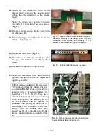
10.
Wipe down the blades of the air exhaust fans with a clean cloth, dampened with
McD ASPC
(HCS)
. Take care not to touch any electrical connections with the cloth. This procedure
ensures efficient fan operation.
11.
Reverse steps to reassemble the unit.
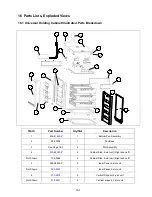
Summary of Contents for Universal Holding Cabinet
Page 46: ...17 1 17 Wiring Diagram UHC...