


15-2
9.
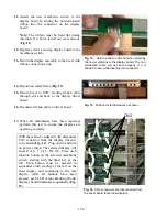
This exposes the transformer, cooling fans, terminal
blocks, fuses and main control board. These
components are accessible and easily
removable/replaceable.
10.
Reassemble the unit by reversing the previous steps.
Ensure all wiring connections are tight and in
accordance with the wiring diagram. Ensure that all
screws and other fasteners are snug.
11.
Before reconnecting power to the unit, clean all
stainless steel surfaces and the interior of the slots
using approved cleansing agents. (
See Appendix B
).
12.
Reconnect power, turn the power switch to the ON
position and reprogram the controllers as necessary to
the desired menu selections.
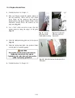
15.2 Replacing Membrane Switch/Switches
Perform steps 1-5 in Section 15.1
1.
Release ribbon cable from top of driver board on left
side of unit. Feed ribbon cable into space between
slots (
Fig. 6-7
).
2.
Remove Allen screw (not on early units) locking
display bezel in place.
3.
Loosen bolt-holding bezel.
4.
Remove bezel, which contains the display, from the
unit (
Fig. 7
).
Fig. 4.
Component shelf slid forward.
Fig. 5.
Component shelf with UHC lid
removed.
Fig. 6.
Remove ribbon cable from driver
board.
Fig. 7.
Feed ribbon cable out of UHC
when bezel is removed.
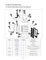
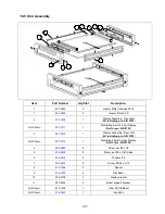
Summary of Contents for Universal Holding Cabinet
Page 46: ...17 1 17 Wiring Diagram UHC...