


15-3
5.
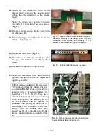
Place bezel face down on table with slot hole
at bottom and remove metal frame holding
display. Note position of rib on metal frame
and position of ribbon connection on display
(
Fig. 8
).
6.
Remove old display assembly.
7.
Clean bezel.
8.
Remove screws connecting the membrane
switch to the display board (
Fig. 9
).
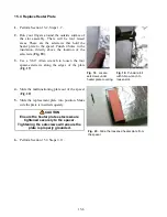
9.
Gently separate the membrane switch from
the display board (
Fig. 10
).
10.
Disconnect the non-terminated ribbon, which
connects the membrane switch to the display
board, by gently pulling the cable from the
connector on the display board (
Fig. 11
).
Note:
Early production units (
prior to S/N
9703
) had the membrane switch soldered
to the display assembly. For these units,
the complete display assembly must be
replaced. (Front Display Assembly: 807-
3309; Rear Display Assembly:
807-3310.)
Fig. 8.
Note ribbon cable is at top of bezel
opening.
Fig. 9.
Remove two screws securing the display
board to the membrane switch.
Fig. 10.
Separate the display board and the
membrane switch.
Fig. 11.
The ribbon on the membrane switch is
pulled free of the connector on the display board.
Summary of Contents for Universal Holding Cabinet
Page 46: ...17 1 17 Wiring Diagram UHC...