


15-4
11.
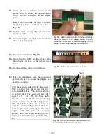
Attach the new membrane switch to the
display board by sliding the non-terminated
ribbon into the connector on the display
board.
Note:
The ribbon must be held flat during
insertion. If it bows, it will not seat correctly
(
Fig. 12
).
12.
Replace screws securing display board to the
membrane switch.
13.
Return the display assembly to the bezel with
ribbon connection at top.
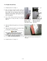
14.
Reposition metal frame (
Fig. 13
).
15.
Return bezel to UHC, feeding ribbon cable
through slot and back to the display driver
board.
16.
Reconnect ribbon cable to driver board.
17.
When all membranes have been replaced,
perform this test to ensure the displays are
operating correctly:
With the cabinet’s sides still off, disconnect
CN2 connector from the display driver(s)
to be tested (
Fig. 14
). Plug unit in and turn
on power switch. The selected display will
show
Disp Test Mode.
Press each
function button on the selected membrane
switch, starting with the timer key at the
left. Each button must be pressed in
sequential order, starting at the left on the
front display and continuing to the rear
display. After all buttons have been
pressed, each LED (Light Emitting Diode)
display should illuminate sequentially (
Fig.
15
).
CN2
Fig. 14.
CN2 connectors are disconnected from
the driver board to test new displays.
Fig. 12.
Hold the ribbon cable flat when attaching
the new membrane to the display board. The non-
terminated cable will not seat properly if it is
allowed to bow while inserting into connector.
Fig. 13.
Position metal framework as shown.
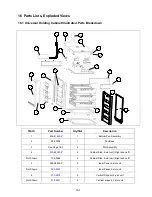
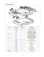
Summary of Contents for Universal Holding Cabinet
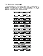
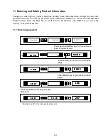
Page 46: ...17 1 17 Wiring Diagram UHC...