ASSEMBLY
OM 0437SB1388-A
18
1. Hydraulic hose
2. Cardboard
3. Magnifying glass
3. Figure 11a:
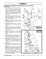
Attach hoses (item 2) to the
hose support previously installed by
running them inside the hose clamp.
4. Figure 11a:
Attach hoses (item 2) to the
hose support located on the three point
hitch with the hose clamp (item 4), a
3/8"NC x 1 1/2" bolt and 3/8"NC nut
(items 3, 5).
5. Figure 11a:
Secure with 1/4" x 15" lg
nylon tie wraps to the illustrated
locations (items 8).
NOTE:
Make sure to leave enough play
to the hoses to allow full rotation of the
chute and that the radius of curvature of
the hoses remains correct. Also make
sure they do not cross and they do not
rub against sharp edges. Rotate the
chute and move the deflector to ensure
that hoses are well assembled.
CAUTION:
To avoid serious personal injury.
Escaping
hydraulic/ diesel fluid under pressure can
penetrate the skin causing serious injury
.
Do not use your hands to check
for leaks. Use a piece of
cardboard or paper to search for
leaks.
Stop engine and relieve pressure before
connecting or disconnecting lines.
Tighten all connections before starting engine
or pressurizing lines.
If any fluid is injected into the skin, obtain medical
attention immediately or gangrene may result
Figure 11a
Summary of Contents for SB1388
Page 1: ...OM0437SB1388 Rev1 11 15 Serial 1XFSB13X_E0140001 plus OPERATOR S MANUAL SNOWBLOWER SB1388...
Page 2: ......
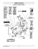
Page 13: ...SAFETY DECALS OM 0437SB1388 A 11 Replace immediately if damaged...
Page 14: ...SAFETY DECALS OM 0437SB1388 A 12 Replace immediately if damaged...
Page 42: ...PARTS OM 0437SB1388 A 40 SNOWBLOWER ASSEMBLY FRONT PART...
Page 44: ...PARTS OM 0437SB1388 A 42 SNOWBLOWER ASSEMBLY REAR PART...
Page 46: ...PARTS OM 0437SB1388 A 44 THREE POINT HITCH...
Page 59: ......

