57
EN
TIG welding
Press the Mode button to select the required TIG mode:
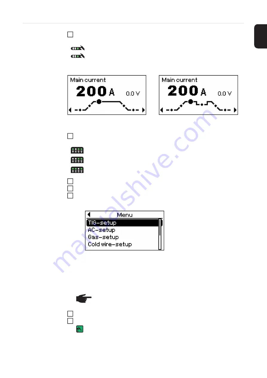
The image for the TIG welding parameter is shown on the display:
TIG welding parameters for 2-step mode (main current
welding parameter selected)
TIG welding parameters for 4-step mode (main current
welding parameter selected)
Only with MagicWave: Press the Mode button to select the required TIG mode:
Use the right arrow key to select the relevant welding parameters
Use the adjusting dial to set the selected welding parameter to the required value
If necessary, additional welding parameters can be set in the set-up menu:
-
Press the menu key
The relevant menu is displayed:
-
Use the adjusting dial to select the desired set-up menu
-
Open the selected set-up menu by pressing the adjusting dial
-
Use the adjusting dial to select the welding parameter
-
To change the welding parameter press the adjusting dial
-
Change the welding parameter value using the adjusting dial
-
Press the adjusting dial
-
Exit the set-up menu
Open the gas cylinder valve
Set the shielding gas flow rate:
Press the Gas test button
The test gas flow lasts for a maximum of 30 seconds. Press the button again to
stop the gas flow prematurely.
-
Turn the adjusting screw on the underside of the pressure regulator until the pres-
sure gauge shows the required gas flow rate
2-step mode
4-step mode
1
AC welding process
AC welding process with automatic cap-shaping function
DC welding process
NOTE!
All welding parameter set values that have been set using the adjust-
ing dial remain stored until the next time they are changed. This applies even
if the power source is switched off and on again in the meantime.
2
3
4
5
6
7
Summary of Contents for MagicWave 2200 Comfort
Page 2: ...2...
Page 4: ...4...
Page 10: ...10...
Page 23: ...General information...
Page 24: ......
Page 27: ...Control elements and connections...
Page 28: ......
Page 39: ...Installation and commissioning...
Page 40: ......
Page 45: ...Welding...
Page 46: ......
Page 89: ...Setup settings...
Page 90: ......
Page 170: ...170...
Page 171: ...Troubleshooting and maintenance...
Page 172: ......
Page 183: ...183 EN Disposal Dispose of in accordance with the applicable national and local regulations...
Page 184: ...184...
Page 185: ...Appendix...
Page 186: ......
Page 195: ...Spare parts and circuit diagrams...
Page 196: ...196 Spare parts list TransTig MagicWave 2200 Comfort...
Page 197: ...197...
Page 198: ...198 Spare parts list TransTig MagicWave 2500 3000...
Page 200: ...200 Spare parts list TransTig 4000...
Page 201: ...201...
Page 202: ...202 Spare parts list MagicWave 4000...
Page 203: ...203...
Page 204: ...204...
Page 205: ...205 Circuit diagrams MagicWave 2200 Comfort V 12 06 2014...
Page 206: ...206 Circuit diagrams MagicWave 2500 Comfort...
Page 207: ...207 Circuit diagrams MagicWave 3000 Comfort...
Page 208: ...208 Circuit diagrams MagicWave 4000 Comfort V 17 12 2012 1 2...
Page 209: ...209 V 17 12 2012 2 2...
Page 210: ...210 Circuit diagrams TransTig 2200 Comfort V 14 12 2010...
Page 211: ...211 Circuit diagrams TransTig 2500 Comfort...
Page 212: ...212 Circuit diagrams TransTig 3000 Comfort...
Page 213: ...213 Circuit diagrams TransTig 4000 Comfort V 17 12 2012...
Page 214: ......
Page 215: ......


