background image

Installation 

Assembly work 


Page 16 

M1010108_en


3.3


Assembly work 

3.3.1


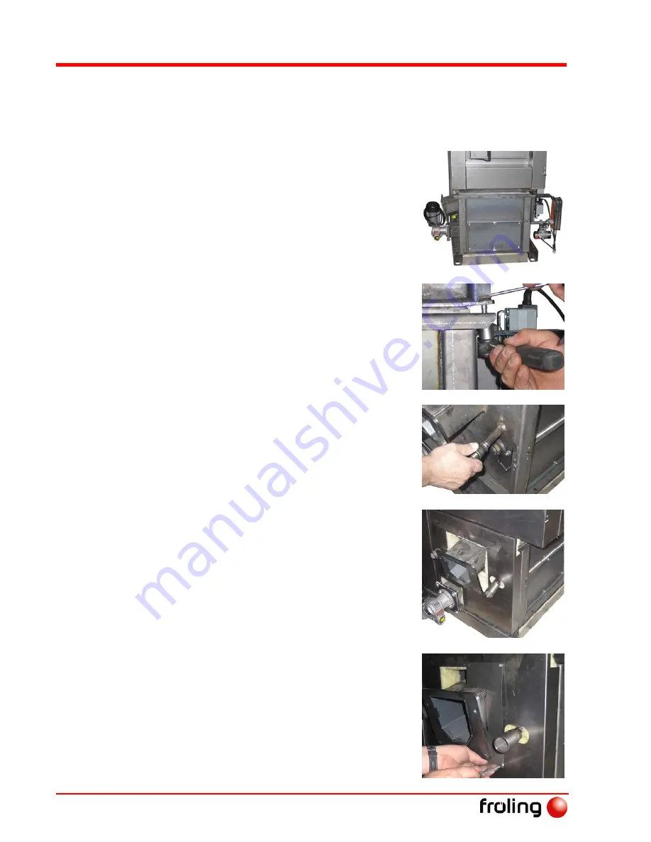
Installing the chamber in the boiler 


The chamber can be installed with the 

stoker connection on the right or the 

left. 


U


Turn the chamber according to the 

discharge side and position on the 

base of the boiler 


Ensure that the seal is centred and 

in the correct position. 


U


Screw the chamber to the boiler 


Ensure an even contact pressure. 


U


Screw reducing socket onto igniter 

tube 


U


Attach insulation on stoker side 

U


Screw in ignition sleeve on reducing 

socket 


Only carry out the following assembly 

step on the G50 stoker shown. If you are 

using a G30 stoker you must first fit the 

stoker 
 

U


Fit the stoker duct cover plates 


Summary of Contents for Turbomatic TMC 28-55

Page 1: ...e 12 A 4710 Grieskirchen Tel 43 0 7248 606 0 Fax 43 0 7248 606 600 info froeling com www froeling com Installation Instructions Turbomatic TMC 28 55 Be sure to read and comply with the operating instr...

Page 2: ...iler The constant further development of our products means that there may be minor differences from the pictures and content If you discover any errors please let us know Subject to technical change...

Page 3: ...nditions generally apply These conditions have been made available to customers and customers have been made aware of them at the time of order completion You can also find the guarantee conditions in...

Page 4: ...oning 14 3 1 2 Temporary storage 14 3 2 Setting up in the boiler room 14 3 2 1 Removing the boiler from the pallet 14 3 2 2 Moving the boiler in the boiler room 14 3 2 3 Minimum distances in the boile...

Page 5: ...rieskirchen Page 5 Tel 43 0 7248 606 0 Fax 43 0 7248 606 600 info froeling com www froeling com M1010108_en C 4 Initial startup Decommissioning 30 4 1 Configuring the boiler 30 4 2 Mothballing 30 4 3...

Page 6: ...s open water heating systems NORM B 8131 Closed water heating systems safety requirements DIN 4751 Parts 1 4 Heating system safety equipment NORM DIN EN 13384 1 Chimneys serving one appliance NORM M 7...

Page 7: ...the building authorities Austria Inform the civic municipal building authorities Germany Register with an approved chimney sweep the building authorities 1 2 2 Requirements for central heating water...

Page 8: ...ith a storage tank as this allows you to achieve continuous reduction within the ideal performance range of the boiler For the correct dimensions of the storage tank and the line insulation in accorda...

Page 9: ...be as short as possible The incline of the connection should not exceed 30 45 Insulate the connection The entire flue gas system chimney and connection must be calculated as per NORM DIN EN 13384 1 o...

Page 10: ...n connection 1210 1310 H15 Height gravity shaft connection with BBF1 RV2 630 595 610 595 H18 Height safety battery connection mm 885 980 B Width of boiler 570 670 B1 Overall width with BBF1 RV2 1730 1...

Page 11: ...Flue gas pipe diameter mm 150 150 B Boiler outfeed connection 6 4 6 4 C Connecting the Thermal Discharge Safety Device 1 2 1 2 D Boiler return feed connection 6 4 6 4 E Connection for filling emptying...

Page 12: ...ation on the fuel is included in the operating instructions in the section on Permitted fuels Test data for operation with wood chips Description Unit 28 35 48 55 Testing institute BLT Wieselburg Test...

Page 13: ...arbon monoxide CO Rated load Partial load mg MJ 31 00 56 00 31 52 65 07 32 48 81 93 33 00 91 00 Nitrogen oxide NOx Rated load Partial load mg MJ 59 00 not measured 64 96 not measured 76 04 not measure...

Page 14: ...rd packaging U Remove boiler from pallet See 3 2 1 Removing the boiler from the pallet 3 1 2 Temporary storage If the system is to be installed at a later date U Store the boiler insulation and contro...

Page 15: ...measures Dimension Description Units 28 55 A Minimum distance from back of boiler to wall 500 B Minimum distance from front of boiler to wall space required for opening insulating door 800 C Minimum d...

Page 16: ...position on the base of the boiler Ensure that the seal is centred and in the correct position U Screw the chamber to the boiler Ensure an even contact pressure U Screw reducing socket onto igniter t...

Page 17: ...n ignition sleeve and hand tighten the retaining screw Take care not to damage the igniter U Fit the flush back hose to the ignition fan using a hose clamp U Lay the hose to connect to the chamber and...

Page 18: ...3 U Attach the cover on the grate shaft side Bundle the motor cables and thread them through the opening in the cover TIP Tie the cables of the individual units to a cable harness using cable ties U F...

Page 19: ...burn back flap C 3 pieces Seals for gravity shaft D Stoker duct seal E Gravity shaft nozzle 15 F Screw set The following steps will guide you through the assembly process when installing a G30 stoker...

Page 20: ...be pre tensioned by 5 delivery configuration See included manufacturer s documentation for how to pre tension the drive U Insert clamping piece as illustrated 90 position and secure at back with fixi...

Page 21: ...locked the flap should fully close and the drive should be pre tensioned 5 See included manufacturer s documentation for how to unlock the drive U Fit the gravity shaft nozzle with seal to the burn ba...

Page 22: ...olts U Attach WOS disc to motor and secure using threaded pin U Position entire unit on boiler at specified holes and secure U Hang the pre tensioning spring at the mount and WOS lever U Attach cable...

Page 23: ...with Turbomatic 48 55 B Flange with ash plate C Ash screw D Ash removal flange for ashcan E Ashcan F Geared motor not shown Rubber seal and screw set NOTICE The components for assembling the ashcan co...

Page 24: ...emble the flange Assembly work on boiler U Fit the geared motor and seal to the flange as illustrated using the hexagonal screws provided Do not tighten the screws yet U Remove the sticky tape and key...

Page 25: ...o the shaft stub U Tighten the screws on the flange and ensure that the worm is correctly aligned U Insert the ash baffle into the boiler 2x guide plates with Turbomatic 48 55 U Position the ash baffl...

Page 26: ...using a half round file and remove burrs U Removing the blind plug U Screw in extension and brass casing U Insert combustion chamber overpressure monitor into the extension and secure with locking sc...

Page 27: ...et must point slightly upwards when not supporting a load as it will be pushed down with the weight of the switch cabinet U Attach cover plate to bracket and secure to insulating side panel U Fit the...

Page 28: ...sing cable ties strain relief U Gather the cables for the boiler sensor door contact switch STL ID fan Lambda probe and WOS drive at the back of the boiler and secure to the insulation with cable ties...

Page 29: ...device must be connected to a pressurised mains water supply in such a way that it cannot be shut off 1 Thermal discharge safety device sensor 2 Thermal discharge safety device opens at 95 C 3 Safety...

Page 30: ...ignment and the steps necessary to modify the control parameters are detailed in the accompanying operating instructions for the boiler control unit 4 2 Mothballing If the boiler is out of service for...

Page 31: ...handed over documentation certificate of conformity U Test heating performed U Commissioning report given to customer U Telephone number for manufacturer s service department indicated U Rating plate...

Reviews: