


3
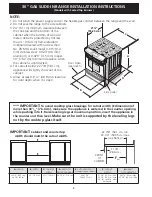
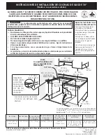
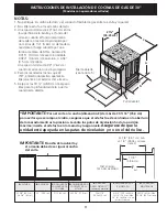
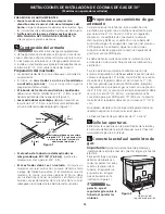
30" GAS SLIDE-IN RANGE INSTALLATION INSTRUCTIONS
(Models with Sealed Top Burners)
Important Notes to the Installer
1. Read all instructions contained in these installation
instructions before installing range.
2. Remove all packing material from the oven
compartments before connecting the gas and
electrical supply to the range.
3. Observe all governing codes and ordinances.
4. Be sure to leave these instructions with the consumer.
5. Note: For operation at 2000 ft. elevations above see
level, appliance rating shall be reduced by 4 percent
for each additional 1000 ft.
Important Note to the Consumer
Keep these instructions with your Use & Care Guide for
future reference.
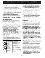
IMPORTANT SAFETY
INSTRUCTIONS
Installation of this range must conform with local codes
or, in the absence of local codes, with the National Fuel
Gas Code ANSI Z223.1/NFPA .54-latest edition.
This range has been design certified by CSA
International. As with any appliance using gas and
generating heat, there are certain safety precautions you
should follow. You will find them in the Use and Care
Guide, read it carefully.
•
Be sure your range is installed and grounded
properly by a qualified installer or service
technician.
•
This range must be electrically grounded in
accordance with local codes or, in their absence,
with the National Electrical Code ANSI/NFPA No.
70—latest edition.
See Grounding Instructions.
•
Before installing the range in an area covered with
linoleum or any other synthetic floor covering,
make sure the floor covering can withstand heat
at least 90°F above room temperature without
shrinking, warping or discoloring.
Do not install the
range over carpeting unless you place an insulating pad
or sheet of ¼" (10,16 cm) thick plywood between the
range and carpeting.
• Air curtain or other overhead hoods, which operate by
blowing a downward air flow on to a range, shall not be
used in conjunction with gas ranges other than when the
hood and range have been designed, tested and listen
by an independent test laboratory for use in combination
with each other.
•
Make sure the wall coverings around the range
can withstand the heat generated by the range.
•
Do not obstruct the flow of combustion air at the
oven vent nor around the base or beneath the
lower front panel of the range.
Avoid touching the
vent openings or nearby surfaces as they may become
hot while the oven is in operation. This range requires
fresh air for proper burner combustion.
Never leave children alone or
unattended in the area where an appliance is in
use.
As children grow, teach them the proper, safe use
of all appliances. Never leave the oven door open when
the range is unattended.
Stepping, leaning or sitting on the
doors or drawers of this range can result in serious
injuries and can also cause damage to the range.
•
Do not store items of interest to children in
the cabinets above the range.
Children could be
seriously burned climbing on the range to reach items.
•
To eliminate the need to reach over the surface
burners, cabinet storage space above the burners
should be avoided.
•
Adjust surface burner flame size so it does not
extend beyond the edge of the cooking utensil.
Excessive flame is hazardous.
•
Do not use the oven as a storage space.
This
creates a potentially hazardous situation.
•
Never use your range for warming or heating the
room.
Prolonged use of the range without adequate
ventilation can be dangerous.
•
Do not store or use gasoline or other flammable
vapors and liquids near this or any other
appliance.
Explosions or fires could result.
• In the event of an electrical power outage, the surface
burners can be lit manually. To light a surface burner,
hold a lit match to the burner head and slowly turn
the Surface Control knob to LITE. Use caution when
lighting surface burners manually.
•
Reset all controls to the "off" position after using
a programmable timing operation.
FOR MODELS WITH SELF-CLEAN FEATURE:
•
Remove broiler pan, food and other utensils
before self-cleaning the oven.
Wipe up excess
spillage. Follow the precleaning instructions in the Use
and Care Guide.
•
Unlike the standard gas range, THIS COOKTOP
IS NOT REMOVABLE.
Do not attempt to remove the
cooktop.
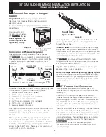
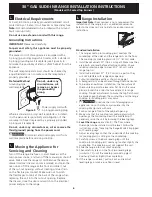
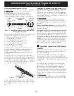
To reduce
the risk of tipping of the
range, the range must
be secured by properly
installed anti-tip bracket
provided with the range.
To check if the bracket is
installed properly, grasp
the top rear edge of the
range and carefully tilt
it forward to make sure
the range is anchored.
• All ranges
can tip.
• Injury to
persons
could result.
• Install anti-
tip device
packed with
range.


