


140.925-IOM (APR 2019)
Page 27
XLP3 EVAPORATIVE CONDENSERS
MAINTENANCE
removed for cleaning. With the BranchLok™ System, tools
are not required to remove the branches.
• Inspect the coil surface. Any corrosion, damage, or
obstructions must be corrected.
• The coil is designed for seasonal dry operation followed
by seasonal wet operation, and not for frequent cycling of
the spray pump. Frequent spray pump cycling may lead to
excessive scale buildup.
With electrical heater tape, heat trace and insulate all exposed
water piping, including pump piping below the overflow level
and make-up water lines.
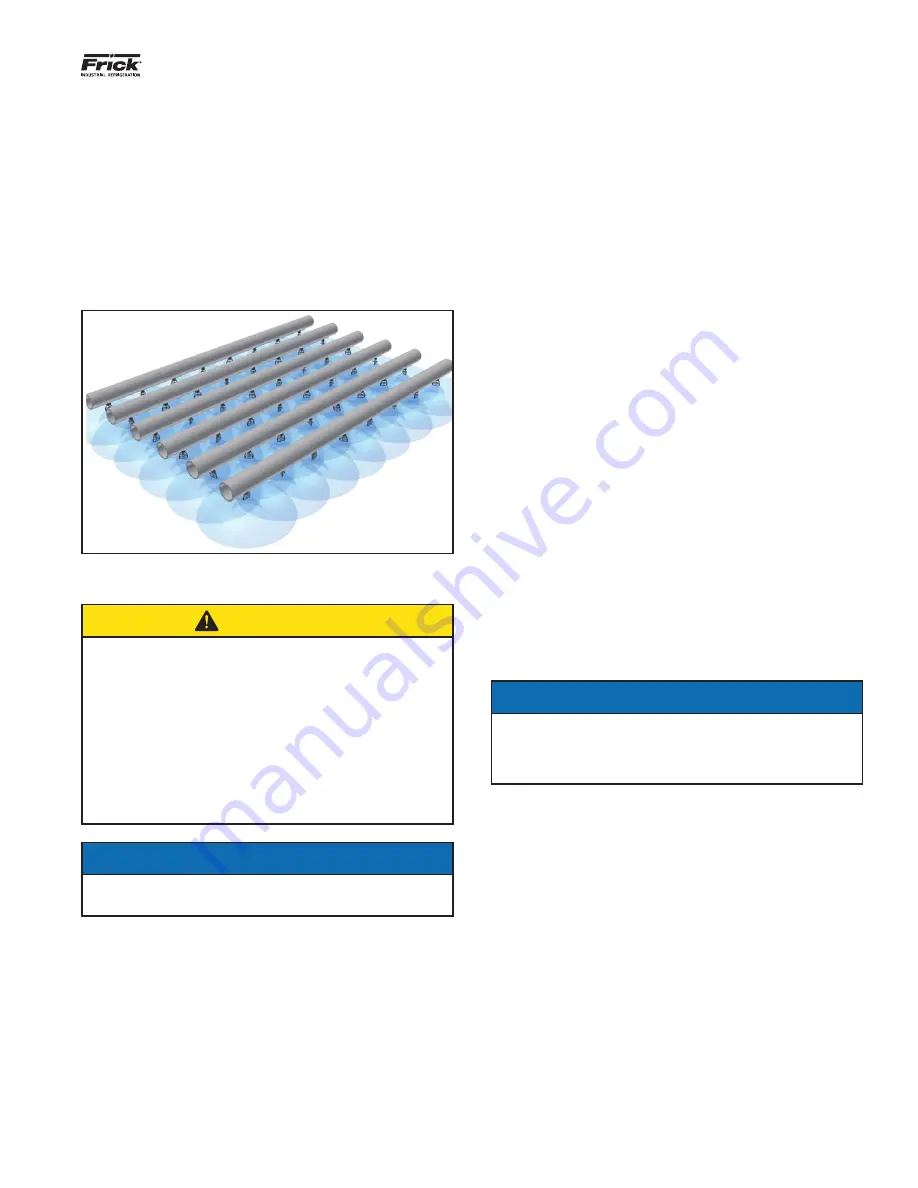
Figure 26 — Nozzle Spray Pattern
CAUTION
Do not use the plastic drift eliminators as a walking,
working, or storage surface. Stepping on or placing
weight on an eliminator can result in physical injury and/
or equipment damage. After ensuring that the fan and
pump motors are locked and tagged out, lift and remove
eliminators as necessary to perform recommended
maintenance and inspections. If access to the top of the
coil is required, place a piece of plywood at least 1/2 inch
thick on top of the coil to protect the surface while
performing the recommended maintenance. When
finished, carefully remove the plywood and re-install any
eliminators which were removed.
NOTICE
Do not use steam or high pressure water to clean PVC
eliminators, fill or materials other than steel.
Water Level Control
There are two types of water level controls used on XLP3
Evaporative Condensers:
• Mechanical make-up valve assembly
• Optional electric water level control package
Mechanical Make-up Valve Assembly
A float-operated mechanical water make-up assembly is fur-
nished as standard equipment on the unit. The standard make-up
assembly consists of a corrosion resistant make-up valve con-
nected to a float arm assembly actuated by a polystyrene-filled
plastic float. The float is mounted on an all-thread rod held in
place by wing nuts. The cold water basin operating water level
can be adjusted by repositioning the float and all-thread rod
using the wing nuts provided.
• Inspect the make-up valve assembly monthly and adjust if
necessary.
• Inspect the valve annually for leakage. Replace the valve
seat if necessary.
• Maintain the make-up water supply pressure between 15
psig and 50 psig for proper operation. Frick recommends a
pressure regulator valve (provided by others) for pressures
over 50 psig.
• Set the initial basin water level by adjusting the wing nuts
so that the make-up valve is completely closed when the
water level in the cold water basin is at the operating level
as stated in Table 4 on page 24.
• With the design thermal load and the average water
pressure (15 to 50 psig) at the valve, the above setting will
produce operating water levels as stated in Table 4 on page
24.
• If the thermal load is less than the design load at the time
of unit start-up, the procedure may produce operating
levels greater than those shown in Table 1. If operating
levels are higher than specified, readjust the float in order
to attain the recommended operating level.
• Closely monitor the water level in the cold water basin and
adjust the level if necessary during the first 24 hours of
operation.
• Operating at the recommended water level will ensure that
the unit basin contains sufficient water volume to prevent
air entrainment in the circulating pump during system start-
up and provides sufficient excess basin capacity to accept
the total system pull-down volume.
NOTICE
If the unit has been ordered with the optional electric
water level control package or is intended for remote
sump application, a mechanical water make-up valve will
not be provided.
Optional Electric Water Level Control Package
As an option, an electric water level control package is avail-
able in lieu of the mechanical make-up assembly. The package
consists of a probe-type liquid level control assembly and a
slow-closing solenoid valve. Stainless steel electrodes, factory-
set at predetermined lengths, extend from an electrode holder
into the cold water basin.
• Clean the stainless steel electrodes periodically to prevent
accumulations of scale, corrosion, sludge, or biological
growth, which could interfere with the electrical circuit.
• The water level is maintained at the recommended
operating level regardless of the system thermal load.
Therefore, it is not recommended that the operating level
be adjusted.
• During the start-up of units equipped with the electric
water level control package, bypass the control unit in
order to fill the unit to the overflow connection.