
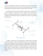


should not be obstructed by nearby trees or buildings. Once you pick an ideal installation
spot, place the mast bracket and wrap it around the mast, clamp the bracket and device together
by tightening the screws through the bolt holes on the back of device and the bracket.
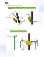
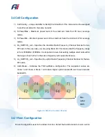
LTE antenna wires need to be pulled from the N-Type connectors on device along four bracket
arms to four antennas on each corner as shown in figure2.2 and the running wires can
be fixed onto bracket arms using bracket ties. It is the best practice to keep all the antenna rods
perpendicular to the bracket branches and to ensure that the four antennas are evenly distributed
in the four corners.
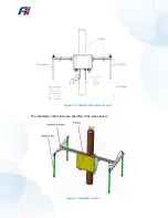
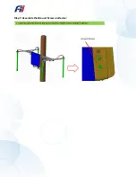
In addition, the GPS antenna should be positioned at a location where the GPS signal
reception is solid and the wire connecting the GPS antenna to the device should be attached to the
pole to ensure the stability of the connection during non-ideal weather conditions. Power
for T99B226 is provided by connecting the power supply to a POE (power on Ethernet) adapter and
through the waterproof ethernet cable to the ethernet port situated next to the antenna ports as
shown in fig2.3. For the same reasons, the wires should be attached to the pole firmly. The
waterproof ethernet port is complied with IP65 regulations which makes it resilient to outdoor
conditions.
LTE Antenna #3
LTE Antenna #4
LTE Antenna #1
LTE Antenna #2
Cable routing on
bracket
Figure 2.2 T99B226 Top view
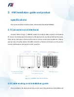
Summary of Contents for T99B226
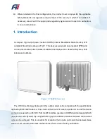
Page 1: ...C Outdoor Small Cell CBRS...
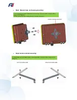
Page 13: ...Step1 Bracket base and housing assembly Step2 Antenna holder assembly...
Page 14: ...Step3 Assembly of the antenna holder with the bracket Step4 Mounting the bracket on a pole...
Page 15: ...Step5 Mounting the device to the bracket Step6 Assemble the Antenna onto the antenna holder...
Page 16: ...Step7 Assemble the Ground Screw on Device...
Page 33: ...How to check the fault record Go to the path Syslog List to check the fault records...
Page 36: ...8 Packing information...


