21
ENGLISH
DESCRIPTION OF FIGURES
Fig. 1 - Overview of the machine.
1) Nameplate.
2) Serial number.
3) Release lever safety brake and insertion cutting ap-
paratus.
4) Device for locking/unlocking lever (3). Only when
pressed in the direction indicated by the arrow, al-
lows the actuation of the lever with the consequent
release of the safety brake and drive of the cutting;
the release, the lever (3) automatically returns
in a vertical position by removing traction to the
transmission belt and activating the braking system
of the cutting. H) Control cable rotating knives. I)
Cable insertion brake.
5) Parking brake lever (only version WM 600 BR).
6) System lock brake (only version WM 600 BR).
7) Lever insertion forward.
8) A device locking/unlocking lever insertion forward.
Only when pressed in the direction indicated by the
arrow, allows the operation of the lever, and acti-
vate the forward run of the machine; the lever is
released, the machine stops and the lever remains
in a vertical position.
9) Lever inserting reverse; (only on version WM 600
BR). The levers 8 and 9, can't be operated simulta-
neously.
10) Throttle Lever: E = stop position of the engine. F =
position of maximum engine rpm.
11) Hand lever handlebar height adjustment (n. 2).
12) Hand lever manual motor controllers.
13) Plug with engine oil dipstick.
14) Fuel tank cap.
15) Hand lever mounting bracket towel rake.
16) Engine air filter.
17) Shelter in canvas with metal frame.
18) Cylinder scatter grass and support cutting knives.
19) No 4 floating knives for cutting grass.
G = direction
of rotation cutting apparatus.
20) Screw fixing the knife float.
21) Towel rake adjustable width.
Fig. 2 - Overall dimensions of the machine.
Fig. 3 - Rod marches.
Push forward all fits 1st gear,
halfway back you insert the second, the whole back
third.
Fig. 4 - Anchor points for lifting the machine.
Fig. 5 - 1) Fixing screws shelter in canvas.
Fig. 6 - Slide cutting height adjustment. 1) Screw
fixing slides. - A) Height of the slide.
Fig. 7 - Safety signs and their location on the machine
(for their description see section 2.2 Safety signs).
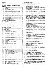
TABLE OF CONTENTS
Declaration of conformity ............................................ 2
SECTION 1. Description and specifications of the
machine
1.1
Foreword. ...................................................... 22
1.2
Warranty ....................................................... 22
1.2.1 Warranty exclusions ..................................... 22
1.3
Identification of the machine
......................... 23
1.4
Description of the machine and authorized ... 23
1.4.1 Use of the machine ....................................... 23
1.4.2 Unauthorized use of the machine .................. 22
1.4.3 Equipment interchangeable on demend ........ 24
1.4.4 Control and driving position .......................... 24
1.5
Protections and safety devices ...................... 24
1.5.1 Noise level ..................................................... 24
1.5.2 Vibrations level ............................................. 24
1.6
Technical specifications
................................ 24
SECTION 2. Safety and prevention
2.1 Safety ............................................................ 25
2.1.1 Words used ................................................... 25
2.1.2 General safety regulation .............................. 25
2.2
Safety signals ................................................ 26
2.3
Safety while operating and maintenaing ........ 26
SECTION 3: Transport
3.1 Transport ...................................................... 27
SECTION 4: Use
4.1
Before using the machine ............................. 28
4.1.1 Unpacking the machine ................................. 28
4.1.2 Installing the whells ...................................... 28
4.1.3 Adjustment of the handlebars ....................... 29
4.1.4. Installing the skids for the adjustment of
tthe cutting height ......................................... 29
4.1.5 Installing a canvas shelter ............................. 29
4.2 Start-up ......................................................... 29
4.3
Progress - engagement of the gear ............... 30
4.4
Innesto fresa e innesto ruota motrice ........... 28
4.4
During operation ........................................... 30
4.4.1 Use of the machinee on slopes ..................... 30
4.4.2 Parking .......................................................... 31
4.5
Stopping of the engine .................................. 31
4.6
After use ....................................................... 31
SECTION 5: Routine maintenance
5.1
General information ...................................... 31
5.2
Engine maintenance ...................................... 31
5.3
Machine maintenance ................................... 31
5.3.1 Maintenance of the chain and the drive belt .. 31
5.3.2 Belt of the cutting device ............................... 32
5.3.3 Safety brake .................................................. 32
5.3.4 Checking the cables ...................................... 32
5.3.5 Replacing the canvas shelter ......................... 32
5.3.6 Replacing the knives ..................................... 32
5.4
Extraordinary maintenance ........................... 33
5.5
Setting at rest ................................................ 33
5.6
Machine dismantling ..................................... 33
5.7
Spare parts ................................................... 33
5.8 Troubleshooting ............................................ 33
Summary of Contents for WM 600 B
Page 5: ...5 Fig 4 Fig 5 Fig 6 1 1 1 A ...
Page 6: ...6 Fig 7 1 2 3 4 5 6 7 8 9 ...
Page 35: ...35 ...

