background image

23 


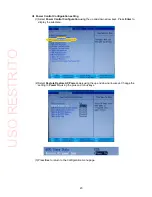
Power Control Configuration setting


(1) Select 

Power Control Configuration 

using the up and down arrow keys. Press 

Enter 

to 

display the submenu. 


(2) Select 

Restore Restore AC Power Loss 

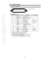
using the up and down arrow keys. Change the 

setting to 

Power On 

using the plus and minus keys. 


(3) Press 

Esc 

to return to the Configuration menu page. 

USO 

RESTRITO

Summary of Contents for VTW-350HS

Page 1: ...OPERATION MANUAL VTW 350HS Video Type Writer 1st Edition USO RESTRITO ...

Page 2: ...2 Edition Revision History Edit Rev Date Description Section Page 1 2014 09 17 USO RESTRITO ...

Page 3: ...ards or a unit malfunction If a foreign material does enter the unit turn the power off and immediately disconnect the power cord Remove the material and contact an authorizedservice representative if damage has occurred Transportation Handle with care to avoid impact shock during transit which may cause malfunction When you need to transport the unit use the original or suitable Caution alternati...

Page 4: ...must be periodically replaced For further details on which parts are consumables and when they should be replaced refer to the specifications at the end of the Operation Manual Since the service life of the consumables varies greatly depending on the environment in which they are Caution used such items should be replaced at an early date For details on replacing consumable items contact your deal...

Page 5: ...The monitor the keyboard and the mouse for controlling VTW 350HS are available for the separate purchase IMPORTANT Do not install any additional software on the VTW 350HS It may cause system malfunction To turn off the VTW 350HS shut down Windows and then press the power switch on the front of the unit When turning back on the VTW 350HS after powering off wait at least 10seconds Check Check to ens...

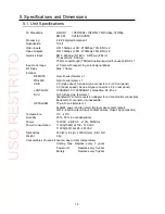
Page 6: ...ons 14 3 1 Connecting Monitor Keyboard and Mouse 14 4 System Adjustment 15 4 1 Selecting Genlock Signal and Adjusting Phase 15 4 2 Output Settings 17 5 Specifications and Dimensions 18 5 1 Unit Specifications 18 5 2 External Dimensions 19 Appendix How to Reset BIOS 20 1 Opening the BIOS Setup Menu 20 2 Main Menu Settings 21 3 Configuration Menu Settings 22 4 Boot Menu Setting 25 5 Saving Settings ...

Page 7: ...iter With its lightweight compact design the VTW 350HS is an extremely portable video typewriter perfect for relay applications The software offers a rich array of drawing functions more than 260 transition functions template control general purpose file interface and more All the functions you need are packed into an extremely compact case With its excellent cost performance the VTW 350HS makes C...

Page 8: ...power switch is turned ON It takes about 5 seconds for the indicator to be lit Wait at least 10 seconds to turn ON after power switch is turned OFF Be sure to shut down Windows before turning OFF this power switch 3 USB1 USB2 Used to connect USB devices such as a keyboard mouse and other USB devices USB2 0 4 RESET If the POWER indicator does not light up green 5 seconds after the power switch is t...

Page 9: ...if unused 3 5 DVI I For digital monitor connection Use the supplied adapter for VGA monitorconnection Bottom DVI I connector is unavailable 6 GPI ALARM For power fan alarm output and the GPIinput output 15 pin D sub female 2 4 1 7 RS232C RS 232C serial port 9 pin D sub male 2 3 2 8 REMOTE RS 422 serial port 9 pin D sub female 2 3 1 9 LAN 1 LAN 2 For the connection to a computer Ethernet port 100BA...

Page 10: ...gnal ground 5 NC No connection 6 SG Signal ground 7 TX Out Transmit data 8 RX In Receive data 9 FG Frame ground 2 3 2 RS 232C 9 pin D sub male Pin Assignment Pin No Signal I O Description 1 DCD Detect carrier detect 2 RXD In Receive data 3 TXD Out Transmit data 4 DTR Out Data terminal ready 5 GND Signal ground 6 DSR In Data set ready 7 CTS In Clear to send 8 RTS Out Request to send 9 RI Ring indic...

Page 11: ...UT Out 5V DC output 9 COMMON Power fan alarm output common 1 10 NC Not used 11 NC Not used 12 GPI IN4 In GPI input 2 Cut 13 GPI OUT2 Out GPI output 3 No use 14 GPI OUT1 Out GPI output 3 No use 15 GND Signal ground The maximum current rating for 5V output is 200mA 1 See Alarm Output Circuit in the following page 2 See GPI IN Circuit in the following page See VTW Software Operation Manual for functi...

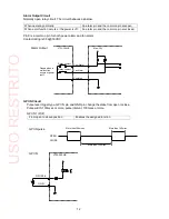
Page 12: ...ting is 0 5A 30VDC Alarm Output VTW 350HS Max 30V Closed when a malfunction occurs or power is off Relay contact Relay contact Pow Alarm Fan Alarm Common GPI IN Circuit Pulse level trigger type GPI IN pin and GND pin change the state from open toclose Pulse width 100msec or more pulse interval 100msec or more GPI IN1 Pin7 From open to closed position Enables the assigned function GPI IN pulse More...

Page 13: ...s voltage should be 12V or less The output current of each GPI OUT pin should be less than 20mA GPI OUT1 Pin14 When function is ON The pin and the ground pin are shorted When function is OFF The pin and the ground pin are open GPI OUT VTW 350HS Max 12V GPI OUT1 2 GND USO RESTRITO ...

Page 14: ...reference signal in GENLOCK IN connector 3 1 Connecting Monitor Keyboard and Mouse Before starting the VTW Software connect a monitor keyboard and mouse as shown below The monitor keyboard and mouse need separate purchase VTW 350HS VTW 350HS Input V VIDEO PGM1 Input K KEY VIDEO PREV KEY VIDEO GENLOCK IN PGM2 KEY GP I A LA RM RS 232C RE MOTE V K P GMV 2 DV I I OUT P UT P GMV 1 PGMK 1 PREV V PREV K ...

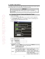
Page 15: ...formation about the installed boards can be seen 4 Select Genlock tab 5 Select a Video format to set the genlock 6 Select a Genlock format BB Black burst TRI Tri level sync 7 Genlock status is indicated Indication Status Remedy LOCK The signal is properly locked The specified reference input is present in GENLOCK IN Not needed UNLOCK The present reference input is not the one specified For example...

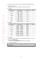
Page 16: ...e is adjusted in lines by using the slider or entering the numeric value Video format Setting Range Step value Default 1080 59 94i 562 lines 562 lines 16 68ms 16 68ms 1 lines 29 66μs 0 1080 50i 562 lines 562 lines 16 68ms 16 68ms 1 lines 35 59μs 0 720 59 94p 375 lines 374 lines 8 34ms 8 32ms 1 lines 22 24μs 0 720 50p 375 lines 374 lines 10 00ms 9 97ms 1 lines 26 67μs 0 525 60 262 lines 262 lines 1...

Page 17: ...es the additive key The key fill will be mixed without attenuation Background Input V and K Allows you to select whether to output the input video and key signals The selection can be made for PGM and PREV separately OFF Outputs only the images generated by the VTW The image will not be mixed with the input video or key signal even if there is an input in the Input V or Input K connector ON Output...

Page 18: ...ries A type connector x 2 on front panel 3 0 Super speed Series A type connector x 2 on rear panel LAN1 LAN2 100BASE TX 1000BASE T compatible RJ 45 x 2 DVI I DVI I Dual Link female x 1 Bundled DVI VGA conversion adapter for a VGA monitorconnection Bottom DVI I connector is unavailable GPI ALARM 15 pin D sub female x 1 ALARM power and fan alarm Relay make contact output GPI 4 input 2 output Input c...

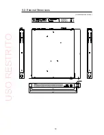
Page 19: ...l Dimensions All dimensions in mm 4 6 4 x12 VTW 350HS VIDEO TYPE WRITER POWE R ACT FAN POW ER ON USB 1 USB 2 RESET O FF 430 462 480 A C10 0 24 0 V 50 6 0 H z IN S E R NO INPUT O UTP UT 6 32 6 44 2 3 500 USO RESTRITO ...

Page 20: ...unit 2 The screen appears as shown below Press the F2 key The F2 key is used to open the BIOS setup menu when BIOS is initialized due to various causes such as the battery failure The F2 key is used to open the BIOS setup menu while the VTW unit is running normally 3 The Phoenix SecureCore Tiano Setup page is opened On the menu bar select the menu page using the right and left arrow keys The Confi...

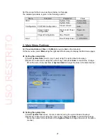
Page 21: ... the menu bar On the menu bar select Main using the right and left arrow keys to display the Main menu page Setting the current date 1 Select System Date month day or year using the up and down arrow keys 2 Enter the current value using the numeric keys and press Enter to confirm the change Move the cursor to the next item of System Date to change the value in the same manner Setting the system ti...

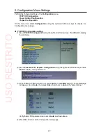
Page 22: ...elect PCI PCIE Configuration using the right and left arrow keys Press Enter to display the submenu 2 Select Processor PCI Express Configuration using the right and left arrow keys Press Enter to display menu parameters 3 To set PEG0 to PEG3 to Auto first press Enter on the PEGO setting The Optionspage will appear Select Auto then press Enter Set others to Auto in the same manner Verify that all P...

Page 23: ...ation using the up and down arrow keys Press Enter to display the submenu 2 Select Restore Restore AC Power Loss using the up and down arrow keys Change the setting to Power On using the plus and minus keys 3 Press Esc to return to the Configuration menu page USO RESTRITO ...

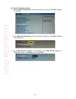
Page 24: ...rrow keys Press Enter to display the submenu 2 Select Memory Configuration using the up and down arrow keys Press Enter to display menu parameters 3 To set Max TOLUD to Dynamic first press Enter on the Max TOLUD parameter to display the Options Select Dynamic then press Enter USO RESTRITO ...

Page 25: ... ATA HDD1 using the up and down arrow keys Use the plus key to move ATA HDD1 to the top of the list 5 Saving Settings and Exiting BIOS Setup Menu Once you have completed the settings press the F10 key A confirmation message appears asking if you want to save the settings and exit the BIOS setup menus Click Yes The BIOS SETUP Menu will close and the Windows restarts with new BIOS settings USO RESTR...

Page 26: ...USO RESTRITO ...

Page 27: ...equipment is operated in a commercial environment This equipment generates uses and can radiate radio frequency energy and if not installed and used in accordance with the instruction manual may cause harmful interference to radio communications Operation of this equipment in a residential area is likely to cause harmful interference in which case the user will be required to correct the interfere...

Page 28: ...M5V 2A2 Canada Phone 1 416 977 0343 Fax 1 416 977 0657 FOR A Latin America the Caribbean 5200 Blue Lagoon Drive Suite 760 Miami FL 33126 USA Phone 1 305 931 1700 Fax 1 305 264 7890 FOR A Europe S r l Via Volturno 37 20861 Brugherio MB Italy Phone 39 039 879 778 Fax 39 039 878 140 FOR A UK Limited Trident Court 1 Oakcroft Road Chessington KT9 1BD UnitedKingdom Phone 44 0 20 3044 2935 Fax 44 0 20 30...

Reviews: