background image

19 

5-3. Web GUI  

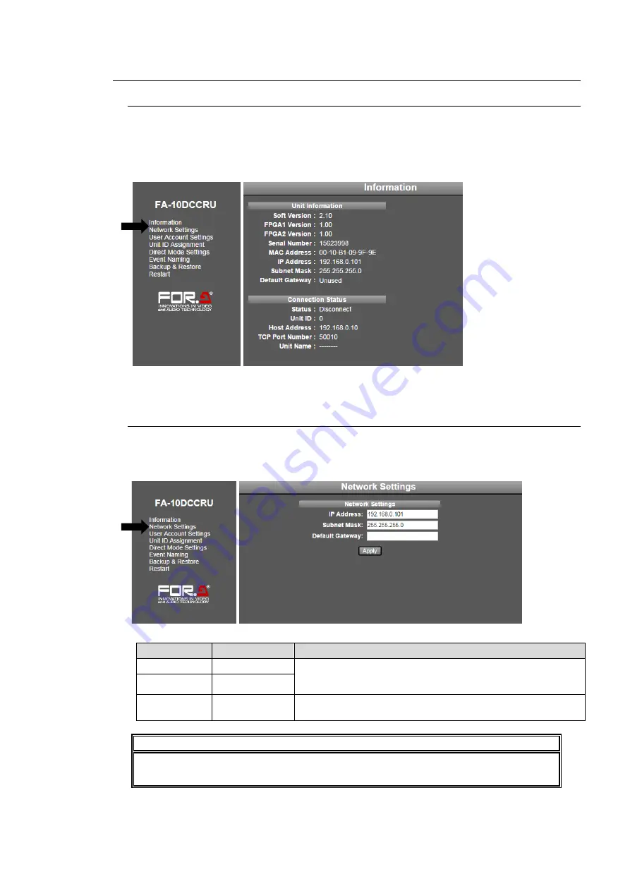
5-3-1. Information 

Click 

Information

 in the left pane to display the Information page, in which Unit Information 

and Connection Status details of the FA-10DCCRU are displayed. 
 

  FA-10DCCRU version, serial number and network setting details  

  Main Unit information 


Click 

Refresh

 to refresh the page. 


5-3-2. Network Settings  

In the left pane of the Web GUI, clicking 

Network  Settings

 displays the Network Settings 

page in the right pane, in which FA-10DCCRU network settings are entered. After settings 
are complete, click 

Apply

 to apply them. 


Item 

Default 

Description 

IP Address 

192.168.0.101 

Allows you to set the FA-10DCCRU IP address and subnet 
mask. Set a unique IP address and connect to a LAN 
network. 

Subnet Mask 

255.255.255.0 

Default 
Gateway 


This setting is not required. Set the Default Gateway 
address according to your network circumstances.  


IMPORTANT 

Network  Settings  are  applied  after  the  FA-10DCCRU  restarts.  See  section  5-3-8. 
“System Restart.”  

Summary of Contents for FA -10DCCRU

Page 1: ...FA 10DCCRU Remote Control Unit 3rd Edition Software Version 3 00 Higher OPERATION MANUAL ...

Page 2: ...Page 1 2014 06 30 1st Edition 2 2014 12 17 Supported FA 505 units Changed event save load procedure 7 2 1 2015 05 29 Changed default IP address to 192 168 0 101 Factual errors corrected 5 2 5 6 3 2016 05 30 Supported HDR in FA 505 2 6 10 6 11 2 6 9 9 6 10 2 3 7 3 ...

Page 3: ...wer cord is firmly plugged into the AC outlet Operation Do not operate the unit under hazardous or potentially explosive atmospheric conditions Doing so could result in fire explosion or other hazardous results Do not allow liquids metal pieces or other foreign materials to enter the unit Doing so could result in fire other hazards or a unit malfunction If a foreign material does enter the unit tu...

Page 4: ...wer cord to avoid potentially hazardous conditions If problems similar to the above occur contact an authorized service representative before attempting to operate the unit again Rack Mount Brackets Ground Terminal and Rubber Feet To rack mount or ground the unit or to install rubber feet do not use screws or materials other than those supplied Doing so may cause damage to the internal circuits or...

Page 5: ...c User manual PDF included Quick Setup Guide 1 Installing the AC Cord Retaining Clip Secure the AC cord with the supplied ladder strap retaining clip assembly to prevent accidental removal from the unit Installing the clip 1 Wrap the retaining clip around the AC cord with the anchor of the ladder strap toward the unit 2 Insert the anchor into the hole next to the AC IN socket 3 Lightly fasten the ...

Page 6: ...ormation 19 5 3 2 Network Settings 19 5 3 3 User Account Settings 20 5 3 4 Unit ID Assignment 21 5 3 5 Direct Mode Settings 22 5 3 6 Event Naming 23 5 3 7 Backup Restore 24 5 3 8 System Restart 26 6 Controlling FA 505 FA 1010 FA 9520 FA 9500 units 27 6 1 Selecting Main Units 27 6 1 1 Connecting a Main Unit in Unit Mode 27 6 1 2 Connecting a Main Unit in Direct Mode 28 6 1 3 Selecting the Connectio...

Page 7: ...es during Split Setting 52 9 7 Messages during Proc Amp Settings 52 9 8 Messages during Color Correction Settings 53 9 9 Messages during Video Clip Settings 54 9 10 Messages during System Settings 55 10 GPI Interface 56 10 1 FA GPIO Editor 56 10 1 1 Installing the FA GPIO Editor 56 10 2 About the FA GPIO Editor 58 10 2 1 Connecting FA GPIO Editor to the FA 10DCCRU 58 10 2 2 Loading and Assigning G...

Page 8: ...quirements for FS Link 70 11 2 Notes on FS Link 70 11 3 FS Link Examples 70 12 Resetting to Factory Default Settings 71 13 Specifications and Dimensions 72 13 1 Unit Specifications 72 13 2 External Dimensions 72 ...

Page 9: ...r correction which can control FA 505 FA 1010 FA 9520 and FA 9500 units Control of up to 100 FA 505 FA 1010 FA 9520 FA 9500 units via Ethernet Coexist with FA 10RU and FA 95RU in a system Direct operation with 14 rotary encoders FA 505 FA 1010 FA 9520 FA 9500 can accept up to 5 FA 10DCCRU control units simultaneously Save up to 100 sets of settings in FA 10DCCRU GPI 30 inputs and 30 outputs Expans...

Page 10: ...ftware Ver 1 00 2 01 Unable to connect with FA 10DCCRU FA 1010 Software Ver 2 22 Able to be controlled with the following functions unavailable BY PASS OPERATE Y Level SPLIT RGB Clip HDR Color Space settings Gamma Range FA 1010 Software Ver 3 00 or higher Able to be controlled with the following functions unavailable RGB Clip HDR Color Space settings Gamma Range Refer to the FA 1010 Operation Manu...

Page 11: ...t Version 1 00 8 00 Unable to connect with FA 10DCCRU Soft Version 8 01 or higher Able to be controlled with the following functions unavailable BY PASS OPERATE Y Level SPLIT RGB Clip HDR Color Space settings Gamma Range Refer to the FA 9500 Operation Manual for details on software version verification ...

Page 12: ...PROCESS CONTROL Allows you to adjust Proc Amp settings in Color Correction mode with CLIP 10 unlit See section 6 8 Process Control and section 6 9 Color Correction Allows you to clip signal levels in Clip mode with CLIP 10 lit using the three center buttons See section 6 10 Clipping Signal Levels The settings apply to the selected FS if controlling an FA 505 FA 1010 or FA 9520 in FA 9520 mode 6 GR...

Page 13: ...DE3 The setting applies to the selected FS by FS SEL in an FA 1010 11 UNITY 2 Pressing the UNITY button resets the value to default Pressing the button again returns the default value to the previous value 12 WHITE CENTER BLACK Selects a gamma curve from WHITE CENTER or BLACK The setting applies to the selected FS if controlling an FA 505 FA 1010 or FA 9520 in FA 9520 mode 13 BAL DIF SEPIA Selects...

Page 14: ...ction 10 GPI Interface for details on GPI connectors 3 Cooling Fan Used to air cool the unit to prevent overheating Do not block the ventilation openings 4 Ground Terminal Used to ground the unit to protect operators against static electricity and or electrical shock 5 AC cord retaining clip anchor hole Used to anchor the AC cord retaining clip 6 AC IN Used for connection to an AC power source via...

Page 15: ...2 F1 F A 9 5 0 0 DISPLAY AREA H D S D F R A M E S YS N C H R O N IZ E R VIDEO IN AUDIO IN GENLOCK REMOTE FAN ALARM DC POWER BY PASS LOCK EVENT ON OFF POWER F1 F2 F3 F4 MASTER CONV2 OUT SEL MODE VIDEO AUDIO ANALOG CONV1 IN SEL DOWNMIX STATUS OTHER C C AES AUDIO CLIP DELAY AUDIO SYS VIDEO SYS AUDIO OP VIDEO OP MAPPING A V O PROCESS SDI AUDIO F4 UNITY UNITY UNITY UNITY F3 F2 F1 F A 9 5 0 0 DISPLAY AR...

Page 16: ...face for details on GPI connectors GPI1 GPI2 GPI3 FA AUX30 Supplied FA AUX30 cables x 3 FA 10DCCRU TO MU 10 100 1000BASE T GPI1 GPI2 GPI3 POWER AC100 240V 50 60Hz IN OFF ON TO MU 10 100 1000BASE T GPI1 GPI2 GPI3 POWER AC100 240V 50 60Hz IN OFF ON FS1 FS2 FS3 FS4 FS5 FS6 FS7 FS8 FS9 FS10 Connect to GPI1 GPI3 connector FA 10DCCRU ...

Page 17: ...168 0 101 in your browser s address bar 4 When the FA 10DCCRU connection is established the Information page will appear 5 2 Changing the FA 10DCCRU IP Address 1 In the left pane of the Web GUI click Network Settings 2 If a login dialog window as shown below appears enter the following user name and password Default User name and Password User name fa10dccru Password foranetwork TO MU 10 100 1000B...

Page 18: ...P address as needed Set a unique IP address and subnet mask in the LAN 5 Click Apply 6 Wait at least 1 second then click Restart in the left pane to display the System Restart page Click Restart in the right pane to restart the FA 10DCCRU New network settings are applied after the restart ...

Page 19: ...rk Settings displays the Network Settings page in the right pane in which FA 10DCCRU network settings are entered After settings are complete click Apply to apply them Item Default Description IP Address 192 168 0 101 Allows you to set the FA 10DCCRU IP address and subnet mask Set a unique IP address and connect to a LAN network Subnet Mask 255 255 255 0 Default Gateway This setting is not require...

Page 20: ...ast 1 second then click Restart in the left pane to display the System Restart page Click Restart in the right pane to restart the FA 10DCCRU The new network settings are applied after the restart IMPORTANT User Account Settings are applied after the FA 10DCCRU restarts See section 5 3 8 System Restart Do not forget your user name or password If you forget your user name or password set the FA 10D...

Page 21: ...r when trying to connect to the unit 3 Enter a unit name not required under the Unit ID number Units names must be alphanumeric and within 15 characters Unit names are displayed on the FA 10DCCRU front panel while selecting a main unit or after connection is established If a unit name is not specified the IP address will be displayed instead of a unit name Change the Port TCP port number setting o...

Page 22: ...ge the Unit ID numbers for MU 1 to MU 5 Click the MU 1 5 button 2 Change the Unit ID numbers for MU 6 to MU 10 then click the MU 2 10 button Change other settings in the same way 3 When all settings are finished click Apply Note that if another page is entered without clicking Apply the settings are ignored IMPORTANT Note that if an IP address is not set under the associated Unit ID number in the ...

Page 23: ...1 Move the mouse over the desired event numbers at the top of the page to display the list Then click on the event numbers Event 1 20 for example 2 Type a new name alphanumeric within 15 characters under each event 3 Click Apply IMPORTANT Do not forget to click Apply When the list display or menu page is changed without clicking Apply the settings in the list are ignored and the event names return...

Page 24: ...gs to another FA 10DCCRU unit See sections 7 2 and 7 3 Backing Up All FA 10DCCRU Settings excluding Event Data Clicking Save in the Config Data area allows you to save all settings as shown below 1 Click Save in the Config Data area to display the Download dialog 2 Click Save in the dialog 3 A Select Destination dialog will appear Specify the destination folder and click Save The FA 10DCCRU settin...

Page 25: ...llows you to save all event data 1 100 in a file 1 Click Save in the Config Data area to display the Download dialog 2 Click Save in the dialog 3 Specify the destination folder and click Save All event data are automatically stored in the file named fa10dccru_evt 1re Change the file name as necessary Restoring Event Data 1 Click the browse button in the Event Data area and select the event backup ...

Page 26: ...K to restart the FA 10DCCRU Note that the following settings require a system restart and that they are applied after the restart Do not forget to restart the FA 10DCCRU Network Settings See section 5 3 2 Network Settings User name or password settings See section 5 3 3 User Account Settings Network Settings from the Backup Restore page See section 5 3 6 Backup Restore ...

Page 27: ...ut 2 seconds later when the selection is confirmed the Unit Name or IP address will also be displayed in a scroll view Display examples ID01 FA 1010 When IP Address and User Name are set under Unit ID 01 ID01 192 168 0 10 No Name When only IP Address is set under the Unit ID number ID01 No Assigned IP Address When nothing is set under Unit ID 01 FA 10DCCRU cannot connect to a unit using Unit ID 01...

Page 28: ...r buttons will blink allowing you to reselect a Direct ID number Display Examples after connection Connected FA 1010 When User Name is set for the connected main unit Connected IP 192 168 0 10 No Name When User Name is not set for the connected main unit Disconnect No main unit is connected See section 5 3 4 Unit ID Assignment for details on Unit Name settings Selecting an MU ID To select a desire...

Page 29: ...ected from FS1 to FS5 When connecting FA 1010 units an FS channel can be selected from FS1 to FS10 When connecting an FA 9520 in FA 9520 mode an FS can be selected between FS1 and FS2 When connecting an FA 9520 in FA 9500 mode an FS cannot be selected 1 Press FS SEL to turn on the button The selected FS number is displayed 2 Use and to change the FS for control When connecting FA 505 FA 1010 units...

Page 30: ...DE3 OFF Displays the image after correction MODE1 Splits the screen vertically and displays images before and after correction MODE2 Splits the screen horizontally and displays images before and after correction MODE3 Displays the image before correction Split can be selected when the FA 1010 software version is 3 00 or higher Split is unable to be set for FA 9520 or FA 9500 NOTE Split is unable t...

Page 31: ... UNITY is applied to all linked FS channels FS Link On See section 8 SYSTEM Settings for more details on setting UNITY mode See section 11 FS Link for more details on FS Linking 6 8 Process Control Proc Amp In this section use the following parameters to perform Proc Amp adjustments VIDEO LEVEL Adjusts the video level Y LEVEL Adjusts the luminance level Y LEVEL can be adjusted when the FA 1010 sof...

Page 32: ...ble using G in Sepia mode Three gamma curves White Center and Black are selectable GROUP ADJ allows you to select between Group adjustment and Individual adjustment When GROUP ADJ is turned off R G and B levels can be set individually When GROUP ADJ is turned on R G and B levels can all be set together by changing R G or B IMPORTANT Color Correction is disabled while in Bypass MU Selection Clip Se...

Page 33: ...hanges are applied to all linked FS channels FS Link On in FA 505 FA 1010 or FA 9520 FA 9520 mode See section 11 FS Link for more details See section 11 FS Link for more details If Color Corrector is remotely set to Bypass by another remote unit FA 10DCCRU or FA 10RU or FA 10GUI the system automatically exits CLIP mode 1 Press CLIP for at least 3 seconds 2 A beep will sound and the CLIP button wil...

Page 34: ...S channels FS Link On in an FA 505 FA 1010 or FA 9520 FA 9520 mode See section 11 FS Link for more details Signal levels and level display The relationship between indicators controls and clip settings are as shown below Y White Clip Level Setting range 50 109 Default UNITY 109 Button Setting Level indicators Panel display Y LEVEL A Lit orange Flashes at 109 UNITY 101 109 B Lit green 100 C Lit ora...

Page 35: ...lashes at 50 1 50 C White Clip Level Setting range 50 111 Default UNITY 111 Button Setting Level indicators Panel display C LEVEL A Lit orange Flashes at 111 UNITY 101 111 B Lit green 100 C Lit orange Flashes at 50 50 99 50 50 0 50 100 111 SMPTE 100 color bars when color 700mVp p C White Clip setting range SMPTE 100 color bars when 100 black 100 50 0 50 7 5 Y Black Clip setting range ...

Page 36: ...ignal levels and level display below Pressing the UNITY button below the value resets the clip value to default 4 Repeat steps 2 and 3 to enter additional adjustments Signal levels and level display The relationship between indicators controls and clip settings are as shown below RGB White Level and White Knee Point affect and interact with each other and change their setting range accordingly RGB...

Page 37: ...loading events Knee Clip Setting Knee Clip allows you to output high luminance areas indicated in green line in the figure above in images with enough resolution indicated in blue line which will be overexposed in traditional methods Knee Clip is mainly used when images are converted from wide color range to small color range The clip levels are calculated on the basis of the OETF Maximum Input va...

Page 38: ... Lit green 0 C Lit orange Flashes at 50 1 50 Black Knee Slope BLACK LEVEL G Setting range Off 15 Default UNITY Off Button Level indicators Panel display BLACK LEVEL G Lit orange Flashes at 15 1 15 Lit orange Flashes at Off UNITY Off When FA 505 Software Version is 1 21 or eariler 1 With CLIP flashing press BAL on the right end of the front panel to enable RGB Clip To disable press BAL again 2 The ...

Page 39: ... Lit green 0 C Lit orange Flashes at 50 1 50 IMPORTANT Note that changes are applied to all linked FS channels FS Link On in an FA 505 FA 1010 or FA 9520 FA 9520 mode See section 11 FS Link for more details 1 5 6 10 11 15 UNIT 16 20 BYPS OP FS SEL MEMORY SET 0 1 2 3 4 5 6 7 FREEZE CLIP SPLIT SELECT SAVE LOAD CLEAR PROCESS CONTROL VIDEO LEVEL Y LEVEL C LEVEL SETUP BLUCK HUE UNITY UNITY UNITY UNITY ...

Page 40: ... enter additional adjustments Signal levels and level display The relationship between indicators controls and clip settings are as shown below EOTF Input Gamma Curve Setting range By pass Rec ITU R BT 709 Rec ITU R BT 1886 Hybrid Log Gamma SMPTE ST 2084 S Log3 Canon Log2 Default UNITY By pass EOTF Electric Optical Transfer Function In Color Space Setting range Rec 709 Rec 2020 Default UNITY Rec 7...

Page 41: ...e EOTF setting Button Setting Level indicators Panel display VIDEO LEVEL A Lit orange Flashes at 65 Variable 65 B Lit green UNITY Variable C Lit orange Flashes at 0 5 0 5 Variable Gamma Range Setting range 25 100 Default UNITY 100 Button Setting Level indicators Panel display VIDEO LEVEL A Lit orange Flashes at 100 100 C Lit orange Flashes at 0 5 25 100 IMPORTANT Note that changes are applied to a...

Page 42: ...lays settings one after another in the following order Video Level Y Level Sepia Level Setup Black Sepia Color Gamma G Level Pressing the button displays settings in the reverse order 6 11 2 When in Clip Mode 6 11 2 1 RGB Clip With the RGB Clip menu displayed pressing and with FS SEL unlit displays the following settings When FA 505 Soft Version is 2 00 or later RGB White Clip RGB Black Clip White...

Page 43: ...Repeatedly pressing the or button displays settings one after another When the end setting is reached the display returns to the top item If the control is turned while displaying settings using the button the changed setting is displayed Pressing the button after that displays the next setting of the setting displayed before the control is turned Example Pressing the button and adjusting SETUP BL...

Page 44: ...FS SEL to complete the change or complete the connection process While Selecting a Unit ID 11 15 UNIT is flashing To enable event operation complete the connection process 7 2 Data Stored in Events When connecting an FA 505 FA 1010 or FA 9520 in FA9520 mode The current FS settings are saved to events When connecting an FA 9520 in FA 9500 mode or FA 9500 The FA 9520 or FA 9500 settings are saved to...

Page 45: ...t memory but are stored in the FA 10DCCRU BYPASS OPERATE FREEZE GRP ADJ FS SEL SPLIT 7 5 Loading Settings from Events Follow the instructions below to load settings Note that the current settings will be lost after settings are loaded 1 When connecting to an FA 505 FA 1010 or FA 9520 select an FS 2 Press the LOAD button A bleep sounds and the event memory number flashes To cancel the operation pre...

Page 46: ...ting items in the following order When the end setting is reached the display returns to the top item Unity Mode Unlinked Front Buzzer Enable GPI Buzzer Enable Display Mode Full Display BRIGHT 30 GPI 1 No 1 10 GPI 2 No 11 20 GPI 3 No 21 30 IP 192 168 0 101 Subnet 255 255 255 0 Gateway 0 0 0 0 FAN Normal Soft Ver 2 10 FPGA1 Ver 1 00 FPGA2 Ver 1 00 Unity Mode Unlinked Back to the top IMPORTANT Note ...

Page 47: ...ndicators No1 10 from 0 to 255 Default 50 GPI2 No 11 20 Rotary encoder 1 Sets brightness for GPI OUT LED indicators No11 20 from 0 to 255 Default 50 GPI3 No 21 30 Rotary encoder 1 Sets brightness for GPI OUT LED indicators No21 30 from 0 to 255 Default 50 IP 192 168 0 101 Display only Displays the FA 10DCCRU IP address Subnet 255 255 255 0 Display only Displays the FA 10DCCRU subnet mask Gateway 0...

Page 48: ...EL G GPI OUT 11 VIDEO LEVEL GPI2 No 11 20 GPI2 Center block GPI OUT 12 Y LEVEL GPI OUT 13 C LEVEL GPI OUT 14 SETUP BLACK GPI OUT 15 HUE GPI OUT 16 WHITE LEVEL R GPI OUT 17 WHITE LEVEL G GPI OUT 18 WHITE LEVEL B GPI OUT 19 BLACK LEVEL R GPI OUT 20 BLACK LEVEL G GPI OUT 21 VIDEO LEVEL GPI3No 21 30 GPI3 Right block GPI OUT 21 Y LEVEL GPI OUT 23 C LEVEL GPI OUT 24 SETUP BLACK GPI OUT 25 HUE GPI OUT 26...

Page 49: ...ing to connect to a main unit in Unit ID Connection mode but no IP address has been set for the specified Unit ID number 6 1 1 ID IP No Name When FA 10DCCRU is connected to a main unit in Unit ID Connection mode and no Unit Name is set for the main unit its IP address is displayed 6 1 1 ID FA 1010 When FA 10DCCRU is connected with a main unit its Unit Name is displayed 6 1 1 Direct Mode Connection...

Page 50: ...r and the main unit cannot be controlled from the FA 10DCCRU To control the main unit change the operation mode to Remote in the main unit 9 2 Messages during Bypass Setting Displayed message Full Simple When information message is displayed Refer to By pass Displayed when the connected FA 505 FA 1010 is set to Bypass 6 2 Operate 1 Displayed when the connected FA 505 FA 1010 is set to Operate 6 2 ...

Page 51: ...n loaded 5 3 6 7 3 Save Event1 Save Event number and name Event1 displayed when saving settings to an event 5 3 6 7 2 Save No Name Save Event number with no name displayed when saving settings to an event 5 3 6 7 2 Saving Same as in Full mode Displayed while saving settings to events 7 2 Saved Event 1 Same as in Full mode Displayed when settings have been saved to an event with no name 5 3 6 7 2 S...

Page 52: ...sage Full Displayed message Simple When information message is displayed Refer to Video Level VL Displayed when the Video Level setting is changed 6 8 Y Level YL Displayed when the Y Level setting is changed 6 8 Y Level No Support Same as in Full mode Displayed when trying to change the Y Level setting of a main unit with no Y Level parameters 2 Chroma Level CL Displayed when the Chroma Level sett...

Page 53: ...evel GR Displayed when the Gamma R Level setting is changed Gamma G Level GG Displayed when the Gamma G Level setting is changed Gamma B Level GB Displayed when the Gamma B Level setting is changed The display is automatically turned off when there is no operation within 1 minute In Full display mode text in parentheses are displayed during menu settings Displayed message Full Displayed message Si...

Page 54: ...nt setting is changed Black Knee Slope BKS Displayed when the Black Knee Slope setting is changed Y White Clip YW Displayed when the Y White Clip Level setting is changed in YPbPr mode Y Black Clip YB Displayed when the Y Black Clip Level setting is changed in YPbPr mode Chroma Clip CW Displayed when the Chroma Clip Level setting is changed in YPbPr mode Input Color Space Same as in Full mode Disp...

Page 55: ... Buzzer Enable Displayed while Front Buzzer is being enabled Front Buzzer Disable Displayed while Front Buzzer is being disabled GPI Buzzer Enable Displayed while GPI Buzzer is being enabled GPI Buzzer Disable Displayed while GPI Buzzer is being disabled Display Mode Full Displayed while Display Mode is being set to Full Display Mode Simple Displayed while Display Mode is being set to Simple Displ...

Page 56: ... Import See section 2 10 1 FA GPIO Editor 10 1 1 Installing the FA GPIO Editor Use the supplied CD ROM to install the FA GPIO Editor software Before installing this software close all other applications on the computer 1 Insert the supplied CD ROM into the PC Click FA GPIO Editor setup on the CD ROM to start the installation wizard 2 Click Next 3 The Software License Agreement window appears Read ...

Page 57: ... installation directory of the FA GPIO Editor is displayed To change the default installation directory click Change and specify a new directory 5 Click Next 6 The last wizard page is displayed Verify the installation settings and click Install to install the software To change settings click on Back change installation settings as required then click Install ...

Page 58: ... be assigned to a port GPI pulse signals can be output inversely and assignments can be performed individually or in groups using Pattern Load In addition GPI settings can be backed up to and restored from files using Export and Import 10 2 1 Connecting FA GPIO Editor to the FA 10DCCRU 1 Click the FA GPIO Editor shortcut icon on the desktop to start FA GPIO Editor 2 When the software window appear...

Page 59: ...assword and click Load 10 2 2 Loading and Assigning GPI Functions As factory default GPI functions are all set to None no function Use the FA GPIO Editor to perform GPI assignments for GPI1 3 Ports 1 30 connectors Select a GPI connector 10 ports by clicking a tab from the following three GPI Port 1 10 FA AUX30 Left Block GPI Port 11 20 FA AUX30 Center Block GPI Port 21 30 FA AUX30 Right Block Note...

Page 60: ...e setting applies to the current FS 6 4 Split Mode Allows you to set Split mode under Setting 2 If an FS is selected under Setting 3 the controlled FS is changed to the selected one and a Split Mode setting is applied to it If None is set under Setting 3 a Split Mode setting applies to the current FS 6 5 CC Mode Allows you to set Color Correction mode under Setting 2 If an FS is selected under Set...

Page 61: ...vent1 100 7 2 Set Setting 2 and Setting 3 according to Setting 1 Input Setting List Port No Setting 1 Setting 2 Setting 3 1 30 None MU Select Disconnect Unit ID1 100 None FS1 FS10 FS Select FS1 FS10 FS Link On Off All Clear FS1 FS10 Freeze On Off None FS1 FS10 Split Mode Off Mode1 3 None FS1 FS10 CC Mode Balance Differential Sepia None FS1 FS10 Gamma Curve Center Black White None FS1 FS10 Clip Off...

Page 62: ...eference input video is detected in the main unit FS1 Input Video Status When an input video for FS1 is present in the main unit FS2 Input Video Status 4 When an input video for FS2 is present in the main unit FS3 Input Video Status 5 When an input video for FS3 is present in the main unit FS4 Input Video Status 5 When an input video for FS4 is present in the main unit FS5 Input Video Status 5 Whe...

Page 63: ...ork connection and settings then click Apply to reenter settings 10 2 7 Pattern Load The Pattern Load function allows you to assign GPIO functions in groups by loading patterns Pattern Load Procedure 1 Click to select a tab from GPI Port 1 10 FA AUX30 Left Block GPI Port 11 20 FA AUX30 Center Block and Port 21 30 FA AUX30 Right Block 2 Click on the Pattern box to select a pattern from the dropdown...

Page 64: ... csv Change the file name as needed then click OK 10 2 9 Importing GPI Settings from Files Select File Import in the menu bar Specify the file name and location Verify settings in the FA GPIO Editor then click Apply to send the settings to the FA 10DCCRU unit See section 10 2 6 Sending GPI Settings 10 2 10 Verifying GPIO Editor Version Click Version Information in the menu bar A window as shown be...

Page 65: ... connected FS Select Button function Description FS1 10 Used for FS selection from FS1 FS10 The LED lights while an FS is being controlled FS Link Select Button function Description FS1 10 Link Used to enable FS Link The LED lights while an FS is linked When the FS cannot be linked an error beep sounds MU ID1 MU ID2 MU ID3 MU ID4 MU ID5 MU ID6 MU ID7 MU ID8 MU ID9 MU ID10 FS1 FS2 FS3 FS4 FS5 FS6 F...

Page 66: ...sed to set Freeze On Off on each FS Split Functions Description Mode Off Mode1 3 Used for Split mode selection Mode Off Mode1 Mode2 Mode3 FS1 FREEZE FS2 FREEZE FS3 FREEZE FS4 FREEZE FS5 FREEZE FS6 FREEZE FS7 FREEZE FS8 FREEZE FS9 FREEZE FS10 FREEZE ...

Page 67: ... IN 13 Input GPI IN 23 Input 11 GPI IN 4 Input GPI IN 14 Input GPI IN 24 Input 12 GPI IN 5 Input GPI IN 15 Input GPI IN 25 Input 13 DC OUT 5 0 V output maximum 200 mA DC 14 GPI OUT 6 Output GPI OUT 16 Output GPI OUT2 6 Output 15 GPI OUT 7 Output GPI OUT 17 Output GPI OUT2 7 Output 16 GPI OUT 8 Output GPI OUT 18 Output GPI OUT 28 Output 17 GPI OUT 9 Output GPI OUT 19 Output GPI OUT 29 Output 18 GPI...

Page 68: ...0 6 GPI Input Control Pulse signals The pulse signal level change OPEN to CLOSE triggers each operation OPEN to CLOSE The assigned function will be turned on OPEN CLOSE 100msec or more PIN 1 7 19 PINs 8 12 20 24 IN FA 1010 inside ...

Page 69: ...that the allowed current for each GPI output circuit is 50 mA and the external power supply should be 5 24 VDC 5 0V Select external or internal power PIN 1 7 19 PINs 2 6 14 18 OUT PIN 13 5 24 V DC external power Protective resistor FA 1010 inside DIP SW setting ...

Page 70: ...ed only to the FS If the FS is linked settings are applied simultaneously to all linked FS channels FS links can be set only by GPI inputs sent from GPI devices such as an FA AUX30 Refer to section 10 2 3 GPI Input Settings for details on how to assign the FS Link function to GPI inputs Refer to section 16 9 Color Correction for details on Color Correction mode Refer to section 6 10 Clipping Signa...

Page 71: ...e as above for FS6 and FS8 4 If FS9 Link is set to On by pressing the FS9 Link button in the previous page FS9 linking is not enabled because Color Correction and Clip mode settings in FS9 are different from those in FS1 FS5 A beep sounds and the FS9 link fails 5 If FS10 Link is set to On by pressing the FS10 Link button in the previous page FS10 linking is not enabled because Color Correction and...

Page 72: ...67 1 replace every 5 years Accessories Operation Manual CD ROM AC cord Rack mount brackets 13 2 External Dimensions All dimensions in mm 480 462 430 40 350 40 44 32 6 6 6 4 30 5 89 5 20 33 140 2 3 1 5 6 10 11 15 UNIT 16 20 BYPS OP FS SEL MEMORY SET 0 1 2 3 4 5 6 7 FREEZE CLIP SPLIT SELECT SAVE LOAD CLEAR VIDEO LEVEL Y LEVEL C LEVEL HUE UNITY UNITY UNITY UNITY UNITY SYSTEM GRP ADJ UNITY UNITY UNITY...

Page 73: ...en the equipment is operated in a commercial environment This equipment generates uses and can radiate radio frequency energy and if not installed and used in accordance with the instruction manual may cause harmful interference to radio communications Operation of this equipment in a residential area is likely to cause harmful interference in which case the user will be required to correct the in...

Page 74: ... of Canada 1131A Leslie Street Suite 209 Toronto Ontario M3C 2J6 Canada Tel 1 416 977 0343 Fax 1 416 977 0657 FOR A Europe S r l Via Volturno 37 20861 Brugherio MB Italy Tel 39 039 91 64 811 Fax 39 039 878 140 FOR A UK Limited Trident Court 1 Oakcroft Road Chessington KT9 1BD UK Tel 44 0 20 3044 2935 Fax 44 0 20 3044 2936 FOR A Italia S r l Via Volturno 37 20861 Brugherio MB Italy Tel 39 039 881 0...

Reviews: