background image

17

GETTING TO KNOW YOUR GRINDER

OPTIONAL PULL GANG BRACKETS

The 

OPTIONAL 

Pull Gang Reel Mount Kit  18574 

consists of a lower mounting bracket that fits over the 

square tooling mounting bar and two threaded locking 

screws.  Attached to this is the upper "V" bracket that 

cradle the reel hub when in position.  There are three 

vertical adjustments on this fixture.  The fixture will 

normally be used in the upper hole position.  

See FIG. 17.

These brackets can be mounted on the square 

mounting bar with offset either forward or backwards, 

but the normal position will be with the "V" centered 

over the bar or with the offset facing the back of the 

machine.  The hold-down swing arm has an upper and 

lower mounting position depending on mower hub 

size.

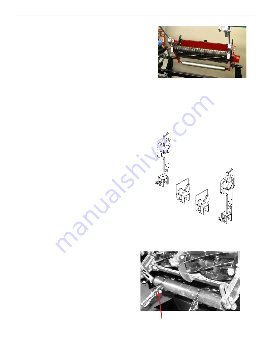
The rear roller of the pull gang mowing unit attaches to 

the roller supports as shown in FIG. 18.

FIG. 16

FIG. 18

CENTER MOUNTING BRACKETS

The centers mounting brackets consist of a stationary 

center bracket and an adjustable center bracket.  The 

stationary bracket will normally be used on the left hand 

side of the mounting bar when facing the reel loading 

position.  See FIG.16.  The centering fixtures are used 

primarily on greens mowers.

FIG. 17

VISE GRIP CHAIN 

CLAMP

Summary of Contents for 6181SRI

Page 1: ...tent No 9 776 297 6 290 581 6 685 544 OPERATOR S MANUAL You must thoroughly read and understand all manuals before operating the equipment paying particular attention to the Warning Safety instruction...

Page 2: ...nd safety signs is not qualified to operate the unit Accidents occur often on machines that are used by someone who has not read the operators manual and is not familiar with the equipment If you do n...

Page 3: ...the machine 6 Read and understand all areas of the Operators manual and review the Assembly Service Manuals and any additional training material if available 7 Understand proper positioning of reel 8...

Page 4: ...se speed control Adjustable Reel Clamping Mechanisms for ease of installation One chain vise grips included to secure any size roller Positive Vertical and Horizontal Reel Adjustments for fast alignme...

Page 5: ...f safety decals 21 DO NOT OPERATE GRINDER WHEN UNDER THE INFLUENCE OF DRUGS ALCOHOL OR MEDICATION 1 KEEP GUARDS IN PLACE and in working order 2 REMOVE WRENCHES AND OTHER TOOLS 3 KEEP WORK AREA CLEAN 4...

Page 6: ...TING SPEED established for the wheel 4 DON T use mounting flanges on which the bearing surfaces ARE NOT CLEAN FLAT AND FREE OF BURRS 5 DON T TIGHTEN the mounting nut excessively 6 DON T grind on the S...

Page 7: ...INSTRUCTIONS COULD RESULT IN PERSONAL INJURY DEATH AND OR PROPERTY DAMAGE 14 KEEP WINCHING AREA CLEAR Do not allow people to remain in the winching area Do not stand between the winch and the load 15...

Page 8: ...CALS LOCATION If any decals are damaged replace them immediately See next page for explanation of symbols and decals 11 17 8 13 1 3 5 7 2 4 6 15 PATENT FIG 2 14 18 10 12 9 14 10 15 9 NEXT TO TRAVERSE...

Page 9: ...wer cord in a manner that removes it as a trip hazard Unplug the machine when servicing or storing for an extended period of time POWER CORD PROTECTION The power supply cord for this product acts as t...

Page 10: ...top Button has been pressed and all movement has come to a complete stop on the machine ENTERING THIS RESTRICTED AREA WHILE THE MACHINE IS RUNNING IS PROHIBITED Appropriate measures should be taken to...

Page 11: ...the machine Check the machine for any instability and make any adjustments if necessary FIG 7 FIG 8 ADJUSTABLE BOLTS LOCATION JAM NUT ADJUSTABLE BOLT FIXED NUT WELDED TO FRAME SET UP GAUGE ASSEMBLY 1...

Page 12: ...nd regulations should be installed by a qualified electrician The plug is classified as a Catagory 0 Main Disconnect Do not wire this machine directly to a power source without a plug or connector unl...

Page 13: ...e 10 Ga Wire For 80 to 140 Feet from panel to receptacle Use 8 Ga Wire For 0 to 15 Meters from panel to receptacle Use 2 5mm Wire For 15 to 42 Meters from panel to receptacle Use 4 0mm Wire FIG 9 WHEN...

Page 14: ...tton is the system start switch Pushing it will engage the magnetic starter and power the control panel The magnetic starter will not engage unless the emergency stop pushbutton is pulled out and the...

Page 15: ...ng the grinding motor traverse motor spin motor etc To restore power pull up on button and press the Start button GRINDING WHEEL MOTOR SWITCH ON OFF Turn the Grinding Wheel Motor on and off Guard door...

Page 16: ...ctly to the frame Insert a bolt through one of the holes in the plate and tighten to a hole or thread in the cutting unit frame See FIG 14 ROLLER SUPPORTS There are two roller supports that are mounte...

Page 17: ...either forward or backwards but the normal position will be with the V centered over the bar or with the offset facing the back of the machine The hold down swing arm has an upper and lower mounting p...

Page 18: ...See FIG 19 Rotate the release arm up to release the belt and rotate the release arm down to engage belt PROXIMITY SENSORS This Grinder is equipped with proximity sensors to limit the travel of the gr...

Page 19: ...er See FIG 23 2 Use the travel limit knob to adjust the stop position of the moveable finger The moveable finger stop needs to be adjusted so that the reel blade makes a smooth transition from the ind...

Page 20: ...e reel to grinding head prior to grinding The set up fixture is designed to be quickly mounted into position and or quickly removed The set up fixture is mounted to the front left corner of the grindi...

Page 21: ...GHTNESS SPECIFICATIONS INITIAL SET UP OF REEL SUPPORTS A The preferred method of mounting fairway units and greens mower units is to set the rear roller on the roller supports facing up with the offse...

Page 22: ...hough it can be adjusted The adjusting cone should be retracted as far as possible to make it easier to secure reels in place OPTIONAL PULL GANG BRACKET SET UP On ground drive mowing units with expose...

Page 23: ...EEL GUIDE REEL AT ARMS LENGTH AND STAND WELL CLEAR OF THE CUTTING UNIT WHEN WINCHING INTO POSITION Slowly raise the mowing unit by cranking the winch handle with the right hand and steadying the reel...

Page 24: ...n the right V bracket if necessary and lower the reel completely into both brackets Secure the right bracket using both locking knobs NOTE On reels that have a square or hexagon shaped hub make sure t...

Page 25: ...he V grooves of the roller supports will be positioned on top of the support bar This application is used primarily for fairway and greens mowers See FIG 36B If the mowing unit back needs to be positi...

Page 26: ...clamp rod under the tubing cross bar as shown in FIG 30 It is recommended to mount them under the tubing cross bar whenever possible Before tightening the overhead clamps you must correctly position t...

Page 27: ...be kept tight 2 If the mowing unit is mounted in centers and only being stabilized by the overhead clamp rods then the clamp rod on the fixed end must be kept tight 3 If the mowing unit is clamped in...

Page 28: ...top or bottom of the reel center shaft See FIG 47 4 Pull rod back and lock Knob C See FIG 46 Traverse to the other side of reel same distance from end Loosen Knob C and extend alignment rod 5 If the l...

Page 29: ...the mounting bar and reel until alignment rod lightly touches the top or bottom of the reel center shaft and then turn the vertical adjusting handwheel an additional 1 2 revolution This 1 2 revolutio...

Page 30: ...indicator rod firmly against the reel shaft move the indicator stop bar back until no contact is made with the indicator rod plunger Now move indicator stop bar forward until contact is made and then...

Page 31: ...e left side dimension the right side dimension is also changing at a ratio to the left side By over compensating at the adjusting end you will compensate for this movement and get the reel aligned muc...

Page 32: ...ding determine the amount the reel is cone shaped This also determines high point for grinding Grinding of a reel must always start at the high point AFTER GRINDING 1 After grinding a reel check the r...

Page 33: ...E COUPLER ADAPTER ASSEMBLY This is mounted to the rubber coupler NOTE If the Drive Coupler Adapter is removed there is a short square drive shaft attached to the Adapter Sleeve This can be used with a...

Page 34: ...pler onto the drive coupler adapter See FIG 62 4 By holding the square drive shaft firmly into position with your left hand you will be able to move the other components to the right and insert the ru...

Page 35: ...the spline adapters included with this grinder If one of these adapters does not work then we recommend this the coupler be welded to a short 1 2 square socket extension Note The 8 tooth spline adapte...

Page 36: ...an act as a dresser to the grinding wheel There can develop what appears to be a very aggressive grind as if the infeed has self infed and then a sudden stop of grinding with no grinding wheel to reel...

Page 37: ...lock handles for locking the grinding wheel vertically Two 2 on the base for the adjusting arm locks and one for grinding wheel vertical height adjustment locking screw See FIG 65 3 Position the heig...

Page 38: ...ection of the grinding wheel Verify that the grinding wheel travels fully off the reel at each end CAUTION IF THE REEL FRAME EXTENDS BELOW THE REEL ITSELF MAKE SURE THE STOP IS SET SO THAT THE GRINDIN...

Page 39: ...reel To spark out the reel infeed the grinding head approximately 002 05 mm one line on the ring scale and let the grinding wheel sparkout During sparkout allow the grinding head to make at least 20...

Page 40: ...PAGE 42 IT SHOWS THE NORMAL REEL HELIX THE HIGH POINT OF THE RELIEF FINGER IS ON THE RIGHT HAND SIDE OF THE GRINDING WHEEL As you look into the guide finger on PAGE 43 IT SHOWS THE REVERSE REEL HELIX...

Page 41: ...he reel from the operator s position you can see the reel blade and its relative position to the grinding wheel By raising the grinding wheel you will decrease the relief angle and conversely by lower...

Page 42: ...helix reels and will wear to match the reel blade helix Normal helix reels are also refered to as Left Hand Side Cutting First Looking from front grass entry position or Right Throw reels Throws gras...

Page 43: ...e right side contacts first you may not relief grind part of the last 3 8 10 mm of the blade NOTE A wheel that has been worn to match a normal helix can generally be removed and reversed to grinder re...

Page 44: ...el blade the relief torque from the spin drive should rotate the reel so the next blade contacts the moveable indexing finger and pushes the indexing finger back against its stop The traverse drive co...

Page 45: ...dure for linear bearings Generally this will be every six months to a year 6 Lubricate the gib area on the grinder carriage base with high quality lithium grease every six months Wipe off excess greas...

Page 46: ...d forth through its range of travel and wipe the shafts after each traverse Repeat until the shafts are dry to the feel This completes the lubrication process LUBRICATION FREQUENCY The lubrication fre...

Page 47: ...near bearings see Lubrication section of manual Remove grinding wheel and spray the movable parts of the finger system Cross slide shafts and adjustment screws Scratches in the paint or any other bare...

Page 48: ...a mild automobile polish Three such products that tend to polish and fill scratches are Johnson Paste Wax Novus Plastic Polish 1 and 2 and Mirror Glaze plastic polish M G M10 It is suggested that a te...

Page 49: ...sition etc Use these values as a guide only REEL MAKE MODEL HEIGHT OF CUT REAR TOOLING MOUNT TYPE REAR TOOLING MOUNT POSITION OVERHEAD CLAMP MOUNT TYPE OVERHEAD CLAMP MOUNT POSITION OVERHEAD CLAMP ROD...

Reviews: