background image

12 

3.3 Display 
 

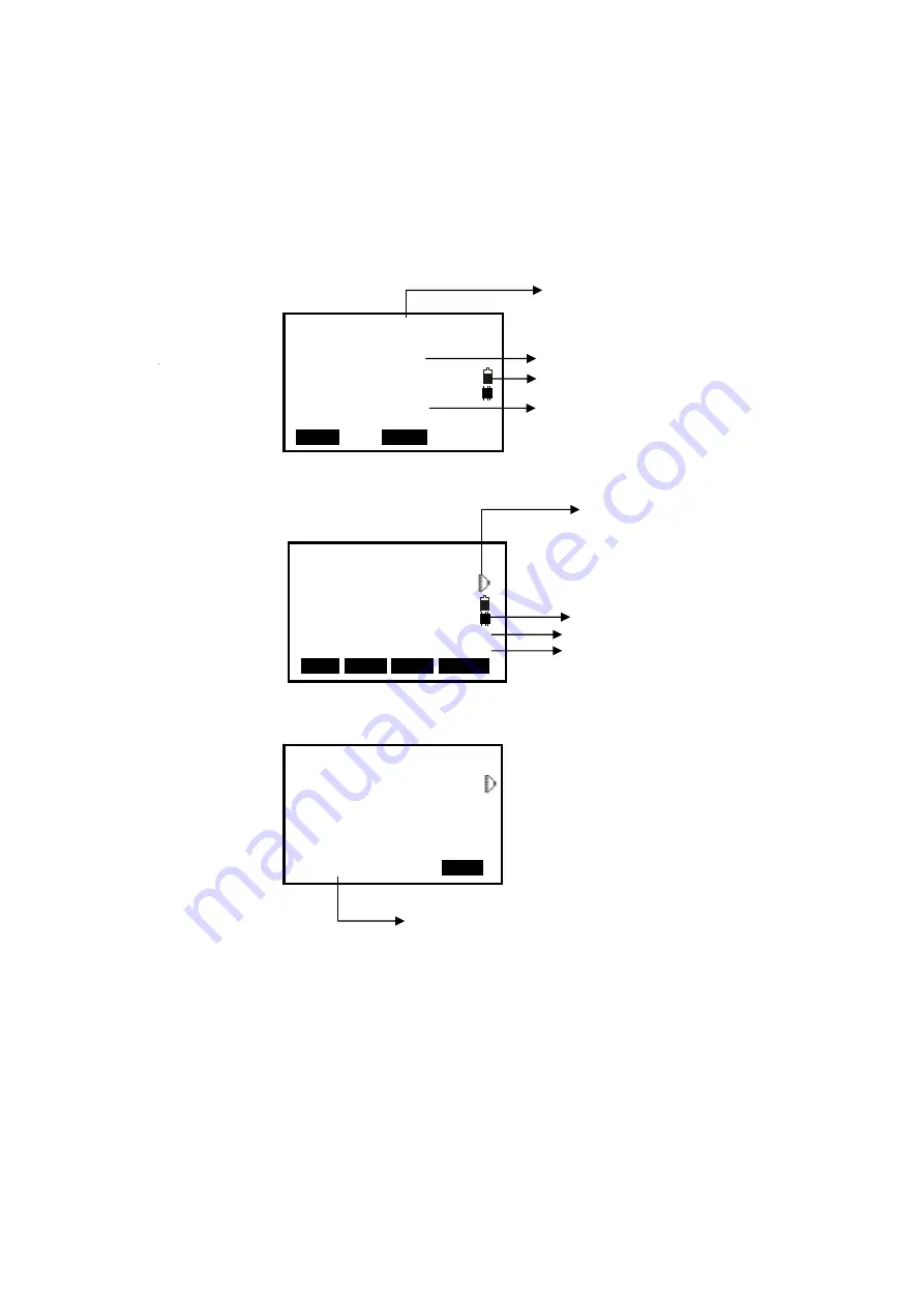
The LCD could display 8 lines with 24 characters per line. In measurement mode, it 
displays some common information in above 7 lines and displays soft functions in the last 
line.  
 
Status screen   


Basic measure mode 


Measuring  


Dist  


Fine                      ppm 0 


-----


STOP


Measuring now 

          FOIF    OTS680 

S/N       Y100006 

Ver       10-04-26 

Date            08/15/2006 

Time      10:01:59 

JOB              JOB1 


MEAS            M E M                    

Application software version 

Instrument model 

Current power
The active JOB

Meas          PC        0.0 

                      ppm      0 


SD 

VA                                            II 

HA                                          P1 

DIST SHV1 SHV2 0 S E T


Target type 

Face II

Page 

Current memory 

Summary of Contents for OTS680 Series

Page 1: ...1 RTS OTS680 Series Total Station Instruction Manual Ver 2 1 1e 2014 01 Suzhou FOIF Co Ltd RTS682 RTS685 L OTS682 R300 R500 R1000 OTS685 R300 R500 R1000 ...

Page 2: ...iable instrument whose performance and design are not surpassed To fully appreciate and protect your investment we suggest that you take the necessary time to read and fully understand this manual We have a dedicated service organization If the need arises please don t hesitate to contact us Thank you for your trust and confidence ...

Page 3: ...wer On Off 14 3 5 Registration Demo Mode 15 3 6 How to Input Number and Alphabet 16 3 7 How to Configure 17 3 8 How to Set Parameters 19 3 8 1 Measure Condition Setting 19 3 8 2 Instrument Basic Setting 20 3 8 3 Communication Port Setting 21 3 8 4 Unit Setting 22 3 8 5 Date Time Setting 23 3 8 7 Key Function Setting 23 3 8 6 EDM Setting 25 4 Angle Measurement 26 4 1 Measure a Horizontal Angle of T...

Page 4: ...Coordinate Resection 52 12 2 Elevation Resection 53 12 3 Resection Calculation Process 55 12 4 Precautions When Performing Resection 56 13 Point Projection 57 13 1 Define Baseline 57 13 2 Point Projection 59 14 Stake out Line 60 14 1 Define Baseline 60 14 2 Stake Out Line Point 61 14 3 Stake out Line Line 62 15 Traverse Surveying 64 15 1 Save Coordinate 64 15 2 Read Coordinate 65 16 Inverse 66 17 ...

Page 5: ...ame a Road File 89 20 7 3 Delete a Road File 90 20 7 4 Delete all Road Files 91 21 Record 92 21 1 Record Occupied Data 92 21 2 Collect Angle Data 93 21 3 Distance Coordinate Data 94 21 4 Record Note 95 21 5 View Data 96 21 6 Select job 97 22 JOB Management 98 22 1 Storage Media Select 98 22 2 Select a JOB 99 22 3 Rename a JOB 100 22 4 Delete a JOB 101 22 5 Output JOB Data 102 22 6 File Copy 103 22...

Page 6: ... 7 Vertical Cross hair on Telescope 117 26 8 Horizontal Collimation Error C 117 26 9 Tilt Sensor 118 26 10 Vertical Index Error 120 26 11 EDM Optical Axis and the Telescope Sighting Axis Error 121 27 Technical Data 123 28 Accessories 129 Appendix I Atmospheric correction formula and chart Just for reference 129 Appendix Ⅱ Correction for refraction and earth curvature 131 Appendix III Connect the T...

Page 7: ...ter power off the instrument Set up the instrument on the tripod When using it please insure the connection between tripod and instrument is firm It is better to work with wooden tripod for the measurement accuracy Assemble the tribrach on the instrument The setting of tribrach would influence the accuracy The tribrach should be check frequently the screw which connects the tribrach and alidade mu...

Page 8: ...n directly The eye injury or blind could result Do not cover the charger Fire could be result Do not use defection power cable socket or plug Fire electronic shock could result Do not use wet battery or charger Fire electronic shock could result Do not close the instrument to burning gas or liquid and do not use the instrument in coal mine Blast could be result Do not put the battery in the fire o...

Page 9: ...t or battery Harmful chemicals could cause burn or blisters Please assemble the tribrach carefully if the tribrach is not stable series damage could result Do not drop the instrument or tripod series damage could result Before use it check the central screw is tight 1 3 Safety Standards for Laser OTS series OTS680 series adopt the class of Laser Product according to IEC Standard Publication 60825 ...

Page 10: ...user of this products is expected to follow all operating instructions and make periodic checks of the product s performance 2 The manufacturer assumes no responsibility for results of a faulty or intentional usage or misuse including any direct indirect consequential damage and loss of profits 3 The manufacturer assumes no responsibility for consequential damage and loss of profits by any disaste...

Page 11: ...on in distance measurement mode is more than in angle mode if the instrument enters into distance measurement mode from angle mode the power maybe auto off because of lower battery The symbol only indicates the supply power but not the instantaneous power change And if the measurement mode changes the symbol will not show the power s decrease or increase immediately It is suggested to check every ...

Page 12: ...t is absolutely necessary to carry out 3 to 5 complete charging discharging cycles and the charging time must be 10 hours at least each time The indicator light on the charger will illuminate three separate colors for varies mode conditions Solid Red Light indicates that the charger is working Solid Green Light indicates that the charge has finished Flashing Red Light indicates no battery on charg...

Page 13: ... with one hand tighten the centering screw on the bottom of the unit to make sure it is secured to the tripod 2 3 Centering and Levelling Up 1 Position tripod legs so that the plummet is aimed to the ground mark point Turn the focusing ring of the optical plummet to focus 2 Turn three footscrews of the tribrach till the center of reticle exactly coincides with the surveying point in any position 3...

Page 14: ...en It is convenient for 670 680 series to level up with electronic level especially when it is difficult to observe the circular level and plate level 1 Power on the instrument and enter into measurement mode press F1 TILT at P3 or press key BS directly and the electric level displays on screen 2 Level it by turning three foot screws see above operation 3 Center the bubble in the plate level Be su...

Page 15: ...re Handle Optical sight Objective Plate level Screen Tribrach Keypad Handle screw Instrument height mark Model label Battery RS 232C port Horizontal motion clamp Horizontal tangent screw Horizontal motion clamp Horizontal tangent screw ...

Page 16: ...10 Plummet Serial number Focusing knob Eyepiece Instrument height mark Leveling screw ...

Page 17: ...ting mode directly Cnfg Enter into config mode directly ESC Escape to the previous menu or mode Shift 1 Shift between number and alphabetic when inputting 2 Shift targets model when measuring BS 1 Delete the character at the left of the cursor when inputting 2 Open electronic level menu Space 1 Input a black space when inputting 2 Input the target or instrument height Func Turn page ENT 1 Select A...

Page 18: ...t functions in the last line Status screen Basic measure mode Measuring Dist Fine ppm 0 STOP Measuring now FOIF OTS680 S N Y100006 Ver 10 04 26 Date 08 15 2006 Time 10 01 59 JOB JOB1 MEAS M E M Application software version Instrument model Current power The active JOB Meas PC 0 0 ppm 0 SD VA II HA P1 DIST SHV1 SHV2 0 S E T Target type Face II Page Current memory ...

Page 19: ...ew 6 JOB select Menu P1 1 Coordinate 2 Stake out 3 Area 4 Offset 5 MLM 6 REM 7 Resection Menu P2 1 Point projection 2 Line stake out 3 Traverse 4 Inverse 5 Polarize 6 Repeat Measure 7 Arc staking out MEM ESC Memory 1 JOB 2 Known data 3 Code 4 Storage Media Select 5 USB 3 1 2 Known data JOB 1 1 Key input 2 Com input 3 Delete 4 View 5 Clear 6 Com setting Code 1 Code Edit 2 Clear List JOB 1 JOB selec...

Page 20: ...F3 Yes it will be turned off press F4 No back to previous screen POWER OFF YES N O 1 FOIF OTS680 S N Y100056 Ver 10 06 21 Date 07 12 2010 Time 10 01 59 JOB JOB1 MEAS M E M Initing Config 1 Meas condition 2 Inst config 3 Inst adjust 4 Com setting 5 Unit 6 Date Time 7 Key Function Inst Config 1 Backlight YES 2 Laser OTS NO 3 LCD contrast 5 4 Reticle lev 7 5 Key Beep YES 6 EDM Signal EDM Inst Config ...

Page 21: ...tration number that you can enter in the No field Press F3 REG key to program resisting screen when you enter the registration number you will see the words Success and the program will run in registered mode If you have no the registration number you can press F4 SKIP to run TS680 in demo mode In Demo mode the program is limited to taking only 10 points Demo mode 10 Data points limited REG SKIP S...

Page 22: ...hows the active input mode you can press the key shift to switch between alphabet and number 2 Input the code in turn and press the blue key ENT to save it You can press key BS to delete your wrong input before the cursor The max length of a code is 16 characters 001 CODEAB 002 003 004 005 006 007 P T O P LAST DEL 001 CODEAB 002 MY01 003 004 005 006 007 P T O P LAST DEL ...

Page 23: ...p Press numeric key 5 then press left key or right key to turn on key beep or not if you select NO you will not hear the beep voice when press any key 6 EDM setting menu Press function key F1 to open the EDM setting menu Inst Config 1 Backlight YES 2 Laser OTS NO 3 LCD contrast 5 4 Reticle lev 7 5 Key Beep YES EDM Inst Config 1 Backlight YES 2 Laser OTS YES 3 LCD contrast 5 4 Reticle lev 7 5 Key B...

Page 24: ...to adjust guide light intensity When Guide light is on it will work in stakeout program according to the light color it is clear to move target to find stakeout point 3 EDM returned Signal Aim at a target then press numeric key 3 and the instrument will beep the EDM returned signal value will display simultaneously Inst Config 1 Trigger key YES 2 Guide light 5 3 EDM signal EDM Inst Config 1 Trigge...

Page 25: ...Item Options 1 Dist mode SD HD VD 2 Tilt adjust XonYon XonYoff XoffYoff 3 Refr coeff 14 20 No 4 VA display Zenith VA V90 5 HA display HAR HAL 6 HA buzzer No Yes 7 Coord N E Z E N Z 1 Min reading 1 5 10 0 0002g 0 001g 0 002g 0 005mil 0 02mil 0 05mil 2 ppm correct No Yes auto correct ppm by sensors or not Code effect The manual input code is available once or always Vdist mode Display mode of vertic...

Page 26: ...t the options 4 Press key ESC back to the previous mode Table 3 2 Option list of basic setting NOTE The options with the symbol are the factory setting Item Options 1 Auto off 30min No 5min 10min 15min The instrument would power off automatically to save battery if no operation in setting time 2 LCD contrast 0 13 9 3 Reticle adjust 0 9 7 Config 1 Meas condition 2 Inst config 3 Inst adjust 4 Com se...

Page 27: ...ck to the previous mode Table 3 3 Option list of com setting Item Options 1 Baud rate 1200 2400 4800 9600 19200 38400 2 Data bits 8bit 7 bit 3 Parity No Even Odd 4 Stop bit 1bit 2bit 5 Check sum No Yes 6 Xon Xoff No Yes 7 Com mode RS 232 B TOOTH Note Every first options with the symbol are the factory setting Config 1 Meas condition 2 Inst config 3 Inst adjust 4 Com setting 5 Unit 6 Date Time 7 Ke...

Page 28: ...key ESC back to the previous mode Table 3 4 Option list of unit setting Item Options 1 Temp 2 Pressure hPa mmHg inchHg mbar psi 3 Angle degree gon mil 4 Dist meter Us feet Int ft Note Every first options with the symbol are the factory setting Config 1 Meas condition 2 Inst config 3 Inst adjust 4 Com setting 5 Unit 6 Date Time 7 Key Function Unit 1 Temp 2 Pressure 3 Angle 4 Dist hPa degree meter ...

Page 29: ...o enter Key Resume menu Key Set the soft key s function at basic measurement mode can be changed 1 Move the cursor to the key change the key s function according to your need by pressing keys to select 2 Press Key OK to confirm the key defined Following items can be defined Config 1 Meas condition 2 Inst config 3 Inst adjust 4 Com setting 5 Unit 6 Date Time 7 Key Function Date and Time Date 08 08 ...

Page 30: ...rement menu MLM Enter missing line measurement menu S O Enter stake out measurement menu TILT Display electronic level REM Enter remote elevation measurement menu HARL Horizontal angle display switching between HR and HL ZA Vertical angle display switching grade and zenith OUT Output the current measurement data via RS 232C port AREA Enter area measurement menu ROAD Enter road measurement menu IHT...

Page 31: ...hree items and press keys to set the options 4 Press key ESC back to the previous mode Table 3 5 EDM setting Item Options 1 Mode Fine r FineAVG 3 Fine s Rapid s Tracking 2 Reflector Prism Sheet No prism 3 Prism const 99 99 4 Temp 30 60 20 22 140 5 Pressure 500 1400hPa 1013hPa 375 1050mmHg 760mmHg 14 8 41 3 inchHg 29 9inchHg 500 1400mbar 1013mbar 7 2 20 3Psi 14 7Psi 6 ppm 499 499 0 Press F1 0PPM to...

Page 32: ...ey to enter EDM setting menu directly 4 Angle Measurement 4 1 Measure a Horizontal Angle of Two Points 1 Sight the 1st target Press F4 0SET twice to set the 1st target as 0 at P1 in the measure mode Press SHV1 or SHV2 to change display status firstly if in distance mode 2 Sight the 2nd target The displayed value is the included angle between two points 2nd target 1st target Meas PC 0 0 ppm 0 SD VA...

Page 33: ...359 5959 mil 0 6399 990 3 Sight the 2nd target The horizontal angle from the 2nd target to the value set as the horizontal angle is displayed NOTE Pressing HOLD performs the same function as above The horizontal angle is in hold status when HOLD is flashing press HOLD again to releasse the hold status Meas PC 0 ppm 0 SD VA 302 5432gon II HA 399 9998gon P1 CORD MENU HOLD H S E T Set H Angle 1 Azimu...

Page 34: ...T to start measure distance 2 The symbol moves continually when measuring distance Distance measuring mode prism const and ppm value are also presented 3 Press F4 STOP to finish measurement The SD HD and VD will display as shown left 4 Press F3 SHV2 SD HD VD and SD VA HA are displayed alternatively Dist Fine ppm 0 STOP Meas PC 0 ppm 0 SD HD II VD P1 DIST S H V 1 SHV2 0SET Meas PC 0 ppm 0 SD 10 329...

Page 35: ...ive factor metal white surface exists between the instrument and the target when measuring the accuracy of the measured results will be affected An angle is also able to be measured when distance measurement Measurement will automatically stop after a single measurement if the EDM mode is single Fine S Rapid S If the distance measurement mode is average Fine AVG the measured distances are displaye...

Page 36: ...Z Target point E 6 1 Input the Occupied Point Data Procedure of inputting occupied point data 1 Measure the height of target and instrument with a tape etc 2 Press F1 CORD at P2 in the measurement mode 3 Select 1 Occ orientation 4 Select 1 Occ coordinate to input the occupied coordinates instrument height and target height in corresponding field Coord 1 Occ orientation 2 Measure 3 EDM 4 JOB select...

Page 37: ...ta saved in the current JOB or in the coordinate search JOB Pt Known point data saved in the current JOB or in the coordinate search JOB P Press keys to move one by one P Press keys to turn the previous next page Press F1 to switch between P status and P status TOP Press it and the first point on the first page will display LAST Press it and the last point on the last page will display SRCH Press ...

Page 38: ...press F1 READ to select existed point data If you input the same coordinates with the occupied point a message Same coordinates will appear and disappear in 5sec please re input the data 3 Press F4 OK to accept the inputted occupied and backsight coordinates the calculated azimuth angle will display 4 Aim at the backsight point and then press F1 MEAS to check the backsight or press F3 REC to recor...

Page 39: ... press F4 OK to set the station but the data will not be recorded 6 3 3D Coordinate Measurement The target coordinate could be measured after the setting of occupied point and backsight azimuth The formular used to calculate N1 N0 S sinZ cosAz E1 E0 S sinZ sinAz Z1 Z0 S cosZ IH TH Where N0 E0 Z0 occupied point coordinates S SD Z Zenith angle Az Azimuth angle IH Instrument height TH Target height S...

Page 40: ...cupied point data You can press F4 REC to record the data 4 Aim at the next target press F2 TAGT to re input the target height if necessary and press F1 MEAS to continue Follow this operation till all targets have been measured 5 Press key ESC back to the coordinate mode Coordinate 1 Occ Orientation 2 Measure 3 EDM 4 JOB select Coord Measure N 1000 000 E 1000 000 Z 10 466 VA 132 3648gon II HA 150 ...

Page 41: ...ured horizontal angle Distance difference Distance Displayed item SD S O SD measured slope distance slope distance of stake out data HD S O HD measured horizontal distance horizontal distance of stake out data VD S O VD measured height difference height difference of stake out data NOTE Stake out data can be input in various modes SD HD VD coordinates and REM measurement EDM settings could be set ...

Page 42: ...n to the position to be stake out Ang included angle between the direction of the reference and the point to be stake out See 4 2 Set the Horizontal Angle to a Required value Press F4 OK to set the input values 6 Horizontally rotate the instrument until dHA is near 0 and set the target on the sight line Menu P1 1 Coordinate 2 Stake out 3 Area 4 Offset 5 MLM 6 REM 7 Resection S O 1 Occ Orientation ...

Page 43: ...an be stake out To get the Z coordinate attach the target to a pole etc with the same target height Procedure of coordinate stake out measurement 1 Press F1 MENU at P2 in the measure mode Select 2 Stake out 2 Select 1 Occ Orientation Input the occupied orientation data see 6 1 Input the occupied point data Then set the azimuth angle of the backsight point see 6 2 Azimuth setting 3 Select 2 S O dat...

Page 44: ...tly above the point to be found then use a measuring tape etc to measure the target height height from the surveying point to the target Press F1 MENU at P2 in the measure mode then select 2 Stake out 2 Select 1 Occ Orientation Input the occupied orientation data see 6 1 Input the occupied point data 3 Select 2 S O data then select 1 Height 4 Input height from the surveying point to the position t...

Page 45: ... out measurement Move telescope to find the point to be stake out Move the telescope near the zenith Move the telescope near the nadir Press key ESC back to stake out mode S O Ht 9 562 SD 10 251m VA 79 6986gon HA 249 0404gon I MEAS R E M ...

Page 46: ...N2 E2 P3 N3 E3 NOTE The number of points 3 30 Make sure these points must be measured or listed clockwise or anticlockwise or mistake will result 8 1 Area Calculation by Measured Data Procedure of area calculation 1 Select F2 MENU 3 Area 2 Area 2 Aim at the first point and then press F4 MEAS Area 1 Occ Orientation 2 Area 01 02 03 04 05 06 07 READ MEAS S P1 P2 P3 P4 P5 E 0 N ...

Page 47: ...ress F4 OK back to menu mode 8 2 Area Calculation by Reading Existed Coordinates Procedure of area calculation 1 Select F2 MENU 3 Area 2 Area 2 Press F1 READ to display existed coordinates data list N 10 000 E 5 000 Z 53 493 VA 152 6296gon HA 62 1314gon 0OK0 MEAS 01 Pt_01 02 Pt_02 03 Pt_03 04 Pt_04 05 06 07 CALC MEAS Area Calculation Pt 4 Area m2 ha 0OK0 Menu P1 1 Coordinate 2 Stakeout 3 Area 4 Of...

Page 48: ...list and press key ENT to set The selected point is set as Pt 01 5 Repeat steps 2 and 4 till all points are selected Make sure read the points clockwise or anticlockwise 6 Press F2 CALC and the calculated area will display Press F4 OK to escape 01 O1 02 Pt1 03 C1 04 Pt2 05 06 07 READ CALC Area Calculation Pt 4 Area m2 ha 0OK0 Occ Pt Coord Pt Pt Pt Pt P T O P LAST SRCH O1 Pt1 C1 Pt2 Pt3 Pt4 Pt5 ...

Page 49: ...tance from the target point to the offset point When the offset point is positioned to the left or right of the target point make sure the angle formed by lines connecting the offset point to the target point and to the instrument station is almost 90 When the offset point is positioned in front of or behind the target point installs the offset point on a line linking the instrument station with t...

Page 50: ...splay the distance and angle of the target point 9 Press F1 REC to save Press F2 NEZ to display NEZ coordinate Press F3 NO back to step 6 Press F4 YES back to offset mode 9 2 Angle Offset Measurement Sighting the direction of the target point to find it from the included angle Set offset points for the target point on the right or left sides of and as close as possible to the target point and meas...

Page 51: ...fter inputting instrument occupied data see 6 1 Input the occupied point data 5 Accurately sight the direction of the target point and press F4 OK the distance and angle of the target point are displayed 6 After finishing measurement Press F1 REC to save Press F2 NEZ to display NEZ coordinate Press F3 NO back to step 6 Press F4 YES back to offset mode Target point Instrument station Offset point T...

Page 52: ...target point and use the offset points as target 2 Select MENU at P2 in measure mode and then select 4 Offset or press F3 OFST at P3 directly 3 Select 4 Offset 2Dist after inputting the instrument occupied data see 6 1 Input the occupied point data 4 Aim at the 1st target and press F1 MEAS and measured data will display Press F4 OK to accept this value Target point Instrument station Offset point ...

Page 53: ...ess key ENT the angle and distance of the target point are displayed 7 Press F1 REC to save Press F2 NEZ to display NEZ coordinate Press F3 NO back to step 6 Press F4 YES back to offset mode Offset 2Dist SD 13 511m VA 346 9636gon HA 249 0298gon R E C N E Z M NOS Y E S Observe 2nd offset N 10 186 E 10 000 Z 10 000 VA 90 0000gon HA 64 5154gon MEAS MOKS Dist 123456789m ...

Page 54: ... displayed as grade mode 10 1 Measuring Distance between Two or More Points Procedure of measuring 1 Press F2 MENU at P2 in the measure mode Select 5 MLM 2 Aim at the start point P1 then press F4 MEAS and the measured data will display 3 Aim at the target point P2 and press F1 MLM to begin measure SD HD VD will display H2 H1 S2 S1 1 2 V2 V1 Target P2 Start point P1 Target P3 Occupied point Menu P1...

Page 55: ... displayed as the gradient 10 2 Change the Starting Point The previous measured data could be set as the base point for the next operation Procedure of changing the starting point 1 Measure the start point P1 and the first target P2 following above steps 1 2 and 3 2 After measuring the two points press F2 MOVE and press F4 YES to set the last measured point as new starting point or press F3 NO to ...

Page 56: ...of the basic measurement mode then select 6 REM on P1 to enter into REM status 3 Reference point measurement Aim at the prism accurately and press F4 MEAS to measure distance Press F4 STOP and the measured data are displayed Press F4 MEAS to re measure 4 Aim at the target accurately and press F2 REM The height from ground to the target is displayed in Ht Press F4 MEAS to repeat and press key ESC b...

Page 57: ... Yo Zo NOTE All N E Z value or only Z value of the occupied point is calculated by measuring known points Coordinate resection measurement overwrite the N E Z data of the instrument occupied point while elevation resection measurement overwrite Z data only Perform resection measurement see 12 1 Coordinate Resection and 12 2 Elevation Resection Inputted known coordinate data and calculated data cou...

Page 58: ...ess F4 MEAS Press F1 READ to read existed coordinate data 4 Sight the first known point and press F1 DIST to begin measurement If known points number is more than two F2 ANG will display you can confirm the known point by angle measurement 5 Press F4 YES to use the measured data of the first known point Press F3 NO to re measure this point You can also input target height here Resection 1 NEZ 2 El...

Page 59: ...n aim the first point then press F4 YES to set the first known point as backsight point and azimuth press F3 NO to back to measure mode 12 2 Elevation Resection Only Z elevation of an instrument station is dertermined by this measurement Between 1 and 5 known points can be measured by distance measurement only Procedure of elevation resection 1 Press F2 MENU on P2 of the basic measurement mode and...

Page 60: ...int You can also input target height here After finishing two measurements CALC will be displayed 6 Press F1 CALC to calculate Instrument occupied elevation and standard deviation are displayed 7 Press F1 NEXT to add other known points Press F3 REC to record the calculated result Press F4 OK to finish elevation resection Only Z elevation of the instrument occupied coordinate is set N and E values ...

Page 61: ...y treating the average value as the instrument occupied coordinate Calculation begins The normal equation is prepared Hypothetical coordinates are found Instrument occupied coordinates are calculated The measured equation for the angle is prepared Calculation of the Z coordinate The measured equation for the distance is prepared Calculation ends Difference from the hypothetical coordinates 0 5mm N...

Page 62: ...pied and known points the narrower the included angle between the known points Be careful for the points can easily be aligned on the edge of a single circle An arrangement such as shown below is desirable unknown point known point It is sometimes impossible to perform a correct calculation such as shown below When they are on the edge of a single circle take one of the following methods 1 Move th...

Page 63: ...long the baseline from 1st point to 2nd point X direction Offset Distance from point to project to the position at which a line extending from point of project intersects the baseline at right angles Y direction 13 1 Define Baseline Procedure of defining baseline 1 Press F2 MENU at P2 of basic measurement mode 2 Turn to P2 select 1 Point projection X direction Length 1st Pt 2nd Pt Offset Baseline ...

Page 64: ... The grade of the baseline will display 8 Press F2 1 or F3 to change the grade display mode NOTE Defined baseline could be used in both stake out line measurement and point projection Point projection 1 Occ Orientation 2 Define baseline 3 Point projection Define 1st Pt Np Ep Zp Pt READ R E C M E A S OK 0 000 0 000 0 000 Azimuth 300gon HD 10 412m Grade 1 150 1 0 0 HOKD Point projection 1 Occ Orient...

Page 65: ... X direction Offset Distance from point to project to the position at which a line extending from point of project intersects the baseline at right angles Y direction dVD Elevation between the baseline and the projected point Press F1 NEZ to display switching between coordinate and distance data Press F2 REC to record the coordinate as a known data Press F4 S O to switch to stake out measurement o...

Page 66: ...g coordinates of the two points 1 Press F2 MENU on P2 of the basic measurement mode 2 Turn to P2 select 2 Stake out line 3 Input the instrument occupied data see 6 1 Input the occupied point data 4 Select 2 Define baseline following operations see 13 1 Define baseline procedures 5 6 and 7 Menu P2 1 Point projection 2 Stake out line 3 Traverse 4 Inverse 5 Polarize 6 Repeat Measure 7 Arc staking out...

Page 67: ...uired point to the position at which a line extending from the required point intersects the baseline at right angles Y direction Procedure of stake out 1 Select 3 Stake out line after defining a baseline 2 Select 1 Point 3 Input values of length and offset then press F4 OK the coordinate of the required point is calculated and displayed Required point Length X direction 1st Pt 2nd Pt Offset Basel...

Page 68: ...red point is from the connected line Make sure to define a baseline before this operation Offline A positive value indicates the point is on the right of the baseline and a negative value indicates it is on the left Cut indicates that the point is below the baseline Fill indicates that the point is above the baseline Length distance along the baseline from 1st point to the measured point Offset ho...

Page 69: ...ta and the baseline displays Ofline A positive value indicates the point is on the right of the baseline and a negative value indicates it is on the left Cut indicates that the point is below the baseline Fill indicates that the point is above the baseline Length Distance along the baseline from the first point to the measured point 6 Aim at the next target and press F4 MEAS to continue the measur...

Page 70: ...1 Save Coordinate Here is the operation of how to measure the foresight point and save it in the list Procedure of saving coordinate 1 Press F2 MENU on P2 of the basic measurement mode 2 Turn to P2 select 3 Traverse 3 Press 1 Save coord Meas PC 0 ppm 0 SD 33 417ft VA 300 9994gon I HA 44 6568gon P2 MENU HOLD HSET E D M Menu P2 1 Point projection 2 Line stakeout 3 Traverse 4 Inverse 5 Polarize Trave...

Page 71: ...cupied point and the previous occupied point becomes the back point 1 Move the instrument to the measured forsight point 2 Select 2 Read coord 3 First aim the previous occupied point then press F4 YES to set the previous foresight point coordinate as the occupied point coordinate or press F3 NO to give up Save coord VD 29 183ft VA 315 3212gon HA 64 5876gon I DIST I H T Save coord VD 19 682ft VA 15...

Page 72: ...3 REC to record the data in the list if necessary You could press F1 READ to read the existed data Press F4 OK to set 4 Input coordinates of the end point See the previous step 5 The inversed value will display Press F3 NEXT to continue press F4 OK back to menu mode Coord Inverse Start point N 1000 000 E 1000 000 Z 39 383 Pt READ R E C 0OK0 Menu P2 1 Point projection 2 Line stakeout 3 Traverse 4 I...

Page 73: ... P2 select 5 Polarize 3 Input the data in corresponding items You could press F1 READ to read the existed coordinate data for start point Press F4 OK to enter 4 The calculated data displays Press F3 REC to record it in the list and press F1 OK back to menu mode N Start point End point D Az Menu P2 1 Point projection 2 Line stake out 3 Traverse 4 Inverse 5 Polarize 6 Repeat Measure 7 Arc staking ou...

Page 74: ...rget A using the horizontal clamp and tangent screw and press the F3 FREE key 8 Recollimate the target B using the horizontal clamp and tangent screw press the F4 HOLD key 9 Repeat 7 to 8 to measure the desired number of repetition Menu P2 1 Point projection 2 Line stake out 3 Traverse 4 Inverse 5 Polarize 6 Repeat Measure 7 Arc staking out Angle Remeasure OK YES N O Angle Remeasure 0 Ht 0 00 00 H...

Page 75: ...ed up to 3600 00 00 minimum reading horizontal angle right In case of 5 second reading horizontal angle can be accumulated up to 3599 59 55 Error will be displayed when the results differ from first measurement by more than 30 Angle Remeasure Exit OK YES N O Angle Remeasure 4 Ht 180 40 00 Hm 45 10 00 0SET MEAS FREE H O L D ...

Page 76: ...ment will help you move the rod to the arc Here S P Start point of arc E P End point of arc C P Circle center point of arc Length Following arc direction distance from arc start point to projective point on arc Ofline Shortest distance between measured point and arc that is the distance on the perpendicular line from measured points to projective point on the arc ...

Page 77: ...re a point whose length and Offline related to the arc can be calculated 5 Press F3 S O to enter stake out measurement screen press F2 or F3 to switch in different modes S O mode One point with input length and offline can be stake out E A mode Some points with same input chord length can be stake out E S mode Some points with same input arc length can be stake out S O mode Arc Stakeout 1 Occ Orie...

Page 78: ...ss F4 MEAS to measure the target the length and offset between the arc and measured point will be displayed Distance from measured point to arc which is on the telescope objective direction Height difference between measured point and projective point on arc Length Following arc direction distance from arc start point to projective point Ofline Shortest distance between measured point and arc that...

Page 79: ...ordinate as stake out coordinate Press F4 OK to set the data 5 Press F3 S O to enter stake out measurement screen press F2 or F3 to switch in different modes S O mode One point with input length and offline can be stake out E A mode Some points with same input chord length can be stake out E S mode Some points with same input arc length can be stake out S O mode Arc Stakeout 1 Occ Orientation 2 2p...

Page 80: ...ss F4 MEAS to measure the target the length and offset between the arc and measured point will be displayed Distance from measured point to arc which is on the telescope objective direction Height difference between measured point and projective point on arc Length Following arc direction distance from arc start point to projective point Ofline Shortest distance between measured point and arc that...

Page 81: ...Select 2 Road File Rename 3 Road File Delete 4 Road Initialize HCurve Start Point STATION 0 000 Np 0 000 Ep 0 000 Zp 0 000 0OK0 StartPine Height TOP LAST DEL ADD RoadCal Calc STATION 0 000 SPAC 10 000 WIDE PEG ENT Type EndPile DEL LINE CIR CURV Road File Select ROAD1 0 ROAD2 0 ROAD3 0 ROAD4 0 ROAD5 0 Road File Rename ROAD1 Road File Select ROAD1 0 ROAD2 0 ROAD3 0 ROAD4 0 ROAD5 0 Clear all roads Se...

Page 82: ... Horizontal Elements Three types elements can be input including line curve and spiral 20 2 1 Input Line Element 1 Make sure the instrument is in horizontal elements editing menu press F2 to display line element inputting menu Input the line length and azimuth in the Dist and Azimuth filed Press F4 ENT key to confirm Road Calculation 1 Input the parameter 2 Road Setout 3 Road file Road Define 1 Ho...

Page 83: ...inputting menu Input the curve parameters including length Dist radius Rad azimuth Azimuth and turn Turn 2 Press F4 ENT key to confirm back to the horizontal elements menu Here EndPile means the end station of this element NOTE 1 Normally the azimuth will calculate and display following previous element 2 When you set the turn move the cursor to Turn item press or key to shift between Left and Rig...

Page 84: ...piral its start radius is default as if you set the direction is OUT here the inputted is start radius of spiral its end radius is default as 20 2 4 Road Horizontal Element Editing In the horizontal element editing menu the inputted element can be edited Delete horizontal element 1 Move or key the cursor will move to different element 2 Press F1 DEL to delete the selected element the two elements ...

Page 85: ...key back to previous menu Type EndPile Line 100 000 Spiral 200 000 Circle 300 000 Spiral 400 000 Line 500 000 DEL LINE CIR CURV Type EndPile Line 100 000 Spiral 200 000 Circle 300 000 Spiral 400 000 Line 500 000 DEL LINE CIR CURV Line Input CIRCLE Dist 200 000m Rad 100 000m Azimuth 0 00 00 Turn RIGHT Direction IN ENT Type EndPile Line 100 000 Spiral 300 000 Circle 400 000 Spiral 500 000 Line 600 0...

Page 86: ...ertical Curve to vertical elements editing menu Here Press F1 FIST key the cursor will move to the first element Press F2 LAST key the cursor will move to the last element Press F3 Del key to delete the selected element Press F4 ADD key to add a new vertical element 2 Press F4 to display Vertical road element inputting menu Input the parameter for vertical element Press F4 ENT key to confirm VCurv...

Page 87: ...ey the cursor will move to different element 2 Press F3 DEL to delete the selected element the two elements adjacent with deleted one will connect automatically For the example after delete the second element the vertical road curve figure is shown below VCurve Element STATION 200 000 Ht 625 000 Lengh 250 ENT StartPile Height 0 000 600 000 FIST LAST DEL ADD StartPile Height 0 000 600 000 200 000 6...

Page 88: ... After all the horizontal elements are confirmed press ESC key back to previous menu For the example after edit the second element the vertical road curve figure is shown below StartPile Height 0 000 600 000 200 000 625 000 400 000 570 000 500 000 685 000 FIST LAST DEL ADD VCurve Element STATION 200 000 Ht 625 000 Lengh 180 m ENT StartPile Height 0 000 600 000 200 000 625 000 380 000 570 000 480 0...

Page 89: ... road wide inputting menu 4 Input the parameters of road width STATION the road will take this width begin from this point to next road width element Lwide left width Rwide right width Press F4 ENT key to confirm 5 Repeat step 4 to input other road width 6 Press ESC back to road calculation menu SPile LW FIST LAST DEL ADD RoadCal Calc STATION 0 000 SPAC 0 000 m WIDE PEG ENT Road Define 1 Horizonta...

Page 90: ...l move to the first element Press F2 LAST key the cursor will move to the last element Press F3 Del key to delete the selected element Press F4 ADD key to add a new vertical element 3 Press F4 ADD to enter road wide inputting menu 4 Input the parameters of road width STATION the road will take this width begin from this point to next road width element Lwide left width Rwide right width Press F4 E...

Page 91: ...ill display until Cal complete appear the program go back to previous menu automatically NOTE If following display it means there are some staked points exist in this file already Press F3 YES key to cover these points or press F4 NO back to previous screen RoadCal Calc STATION 0 000 SPAC 20 000 m WIDE PEG ENT Road Define 1 Horizontal Curve 2 Vertical curve 3 Road Calculation OVERLAP YES NO ...

Page 92: ... to move cursor to display adjacent pages Press F2 TOP key to move cursor to first station Press F3 LAST key to move cursor to last station Press F4 SRCH key to enter the serial number PT to look for the station 4 Press F4 ENT to display the coordinate of selected station PT Station serial number Code Station mileage C means center station R means right station L means left station Press F1 NEXT k...

Page 93: ...ation mileage C means center station R means right station L means left station Press F1 READ key to open the station list Press F2 PREV key to display previous station Press F2 NEXT key to display next station 4 Press F4 ENT to enter coordinate staking out screen see chapter 7 2 Coordinates Stake out Measurement to do that Road RoadCoordSO Pt 1 Code 0 000C Np 0 000 Ep 0 000 Zp 600 000 READ PREV N...

Page 94: ...e 3 select 1 Road Calculation enter road menu 2 Select 3 Road file to road file management menu 3 Select 1 Road File Select to display road file list the cursor will stay on current Job file 4 Press or arrow key to move cursor after reach to the job you want to select press ENT key to confirm The program will back to road file management menu automatically Road Calculation 1 Input the parameter 2 ...

Page 95: ...rrent road file will display 4 Input new name press ENT key to confirm The program will back to road file management menu automatically NOTE The max length of road file name is 8 characters special symbols can not be accepted such as Road Calculation 1 Input the parameter 2 Road Setout 3 Road file Road file 1 Road File Select 2 Road File Rename 3 Road File Delete 4 Road Initialize Road File Rename...

Page 96: ...o confirm to delete press F3 NO back to file list the file will not be deleted 5 Press F4 YES to delete this file all the inputted and calculated data in this file will be cleared and the file name change to initial status Road Calculation 1 Input the parameter 2 Road Setout 3 Road file Road file 1 Road File Select 2 Road File Rename 3 Road File Delete 4 Road Initialize Road File Select P1 ROAD1 9...

Page 97: ...eted 4 Press F4 YES to delete all road files Initing will display at last it will back to road file management menu automatically NOTE Pay more attention to this operation after initialization all the files back to initial status the deleted elements and data can not be resumed Road Calculation 1 Input the parameter 2 Road Setout 3 Road file Road file 1 Road File Select 2 Road File Rename 3 Road F...

Page 98: ...an input the following items by hand PT instrument heigt Inst H code N0 E0 Z0 user date time weather wind temperature pressure and ppm Press key to select item or press FUNC to turn page Press F1 READ to read coordinate from memory See 6 1 Input the occupied point data Press F2 RES to enter resection program and get the station coordinate Press F3 REC to record the station coordinate into memory A...

Page 99: ...Psi The ppm range 499 499 ppm 21 2 Collect Angle Data 1 Enter into record mode The active JOB will display 2 Select 2 Angle data then aim at the target the angle will display in real time 3 Press F4 REC to input the following items point number target height and code press F1 OK to save data You could press F1 AUTO to perform this process directly if PT code and tgt H are unnecessary to re set Pre...

Page 100: ...set 4 Aim at other targets repeat step 3 to collect other points NOTE After performing the process once both distance measurement data and coordinate data are recorded into memory as the same Pt Distance measured data is recorded firstly and then coordinate data is recorded Press FUNC key the screen will switch between coordinate mode and distance mode REC JOB MY 1 Occ data 2 Angle data 3 Collect ...

Page 101: ...OB will display 2 Select 4 Note 3 Input note and press F1 OK to save The max length is 60 characters NOTE Max note length is 60 characters REC JOB MY 1 Occ data 2 Angle data 3 Collect Points 4 Note 5 View 6 JOB select Meas PC 0 0 ppm 0 SD VA 302 5432gon II HA 0 0000gon P3 EDM OCC OFST R E C REC Note Free 13996 ROAD100 0OK0 ...

Page 102: ...rst point Press F3 LAST key to move cursor to last point Press F4 SRCH key to enter the serial number PT to look for the point 4 Select one and press key ENT to view press ESC back to list NOTE If the point number is the same only the newer recorded data could be viewed The data inputted beforehand could be viewed here REC JOB MY 1 Occ data 2 Angle data 3 Collect Points 4 Note 5 View 6 JOB select ...

Page 103: ...e active JOB will display 2 Select 6 JOB select to set job see 22 1 Select a JOB to operate REC JOB MY 1 Occ data 2 Angle data 3 Collect Points 4 Note 5 View 6 JOB select Meas PC 0 0 ppm 0 SD VA 302 5432gon II HA 0 0000gon P3 EDM OCC OFST R E C JOB selection JOB2 0 S F 1 000000 Coord search JOB JOB3 LIST S F ...

Page 104: ...urrent storage media Or press F2 External SD to set the external SD card as current storage media If the internal card is current storage media will display on screen right If the external SD card is current storage media will display on screen right NOTE 1 If the SD card is first using on the total station when select it as storage media Initialing will take about 30s 2 If there is no SD card in ...

Page 105: ...B1 JOB2 JOB20 you can rename them if necessary Scale factor could be set for every JOB but only the one of the active JOB could be modified Here is the equation used to calculate the data HD2 HD1 S F Where HD2 corrected horizontal distance HD1 measured horizontal distance S F scale factor Procedure of JOB selection and scale factor setting 1 Press F3 MEM in the status mode to enter into memory man...

Page 106: ... enter into memory management 2 Select 1 JOB to enter JOB management 3 Select 2 JOB rename to rename the active JOB 4 Input a new name and press key ENT to save the setting The maximum length of a JOB name is 12 characters JOB selection P1 JOBA JOB1 JOB MY MYJOB JOB B JOB01 JOB C 15 56 20 50 45 2 0 JOB MY S F 0 999998 JOB selection JOB MY S F 0 999998 Coord search JOB CORD1 LIST Memory 1 JOB 2 Kno...

Page 107: ...JOB delete 4 20 JOBs display on three pages The numbers to the right represent the points quantity recorded in each JOB Select the useless JOB that you wanna delete and press key ENT 5 Press F3 NO to give up or press F4 YES to delete the JOB JOB deletion P1 JOBA JOB1 JOB Paul01 MYJOB JOB B JOB01 JOB C0000000 15 56 20 50 45 2 0 JOB C Confirm to delete 0N O0 Y E S Memory 1 JOB 2 Known data 3 Code 4 ...

Page 108: ...o enter into memory management 2 Select 1 JOB to enter JOB management 3 Connect your instrument and computer via communication cable standard component 4 Select 4 Download to enter into com output mode and all JOBs display 5 Select the JOB to be output 6 Press key ENT to start to send out via RS 232C port it will back to JOB list mode after finishing More details see the Help file of FOIFExchange ...

Page 109: ...e pages select one job you want to copy And press ENT key to confirm 4 Press F3 NO to give up or press F4 YES to copy 5 For more information please read the Help file of FOIFExhange on chapter 2 3 Data transfer via SD card JOB deletion P1 JOBA JOBCDD JOB Paul01 MYJOB JOB B JOB01 JOB C000000 15 56 20 50 45 2 0 JOBCDD Confirm to Copy 0N O0 Y E S Memory 1 JOB 2 Known data 3 Code 4 Storage Media Selec...

Page 110: ...ent and PC via USB cable TS680 will display U FUNCTION Stop Press ESC It means the TS680 is connected with PC already Press ESC to disconnect them and the instrument bact to previous menu For more information to see the Help file of FOIFExchane on chapter 2 2 Data transfer via USB slave port Memory 1 JOB 2 Known data 3 Code 4 Storage Media Select 5 USB U FUNCTION Plug the USB Exit Press ESC U FUNC...

Page 111: ...nt 2 Select 2 Known data job list will display Select one Job you want to operate press ENT key to confirm known data menu will display you can see the active JOB on the second line 3 Select 1 Key Input 4 Input point number and coordinates The active job and free memory is displayed at the top right corner Press F4 OK to save settings and continue to input other points Press key ESC back to the kn...

Page 112: ...enu will display you can see the active JOB on the second line 3 Select 2 Com input 4 Run FOIFExchange software PC see the help file of FOIFExchagne to upload known data to current JOB the chapter is 2 1 2 Upload Known data from PC to TS680 internal memory When data transferring the number following Receiving will upgrade continually at last it will back to known data mode after finishing JOB6 Fre...

Page 113: ...oint you want to delete the point coordinate will display 5 Press F1 NEXT to display the next point data Press F2 PREV to display the previous point data Press F4 DEL to delete it and continue to delete other points Press key ESC back to known data management mode Memory 1 JOB 2 Known data 3 Code 4 Storage Media Select 5 USB JOB selection P1 DAFENG 10 JOBFF 3000 WOMENSHI 1256 FATELU 100 KEMEN 560 ...

Page 114: ...oints If it is back light press or key to move cursor to display adjacent pages Press F2 TOP key to move cursor to first point Press F3 LAST key to move cursor to last point Press F4 SRCH key to enter the serial number PT to look for the point 5 The coordinate and point number will display Press F1 NEXT to display the next point data Press F2 PREV to display the previous point data Memory 1 JOB 2 ...

Page 115: ... will display you can see the active JOB on the second line 3 Select 5 Clear 4 Press F3 NO back to known data management Press F4 YES to delete all known points data of the active JOB completely Memory 1 JOB 2 Known data 3 Code 4 Storage Media Select 5 USB JOB selection P1 DAFENG 10 JOBFF 3000 WOMENSHI 1256 FATELU 100 KEMEN 560 JOB6 510 JOB7 0 Clear Confirm to delete 0NO0 Y E S Known data JOB JOB6...

Page 116: ...ve the cursor and input or correct code Here Press F1 P key to change the function of and keys if it is light press or to move cursor between adjacent codes If it is back light press or key to move cursor to display adjacent pages Press F2 TOP key to move cursor to first code Press F3 LAST key to move cursor to last code Press F4 DEL key to selected code NOTE The codes recorded in memory could be ...

Page 117: ...3 Select 2 Clear list 4 Press F3 NO back to previous mode Press F4 YES to delete all codes recorded in memory of all JOBs completely 5 If you select 1 Code Edit you will find no code inside Clear all codes Confirm to delete 0NO0 Y E S Memory 1 JOB 2 Known data 3 Code 4 Storage Media Select 5 USB Code 1 Code Edit 2 Clear list 001 002 003 004 005 006 007 P T O P LAST DEL ...

Page 118: ...nt again Change 1st obs During missing line measurement the observation of the target was not completed normally Sight the target accurately and press MLM to perform the measurement again Need prism obs During REM measuring the observation of the target was not completed normally Sight the offset point accurately and press MEAS to perform the measurement again No Free Space There is no more space ...

Page 119: ...1 Select a point B on the approximately horizontal line AC with about 100 meters long Measure the distances of lines AB AC and BC 2 The instrument constant can be calculated instrument constant AB BC AC 3 Repeat steps 1 and 2 ten times and get the average value for instrument const if the average value is within 3mm adjustment is unnecessary 4 If the difference is over 3mm after the preceding oper...

Page 120: ...s then adjust the two screws to center the bubble 4 Turn the instrument 180 200gon adjust the Adj screw with adjustment pin slightly to correct half of the bubble s displacement when it doesn t move 5 Repeat operations 3 4 until the bubble remains centered in any position 26 3 Circular Level Ⅰ Check 1 Mount the instrument on a stable device and fix it 2 Level it accurately by the plate level 3 Obs...

Page 121: ...nd fix it 2 Set a cross mark under the instrument 3 Coincide the center mark of the optical plummet with the cross mark by adjusting three leveling foot screws 4 Turn the instrument 180 200gon check the center mark and cross mark if they are coincide no adjustment is necessary if not adjust it Ⅱ Adjustment 1 Set the instrument on stable device and fix it 2 Set a cross mark under the instrument 3 U...

Page 122: ... cross mark if they coincide adjustment is not required Otherwise adjust it 2 Adjustment Setting up the instrument on the checking tool or tripod which is 1 5m apart from ground Turn on laser plummet turn tribrach foot screws until laser spot coincides with cross mark If you use tripod make a cross mark on the laser spot directly Rotate instrument 180 around if the laser spot is over 2mm apart fro...

Page 123: ...ce section so that the vertical cross hair coincides to point A finally re tighten the four screws 5 Repeat the checking and adjusting until there is no deviation NOTE After the adjustment of cross hair please check the collimation error and vertical index error see 27 11 EDM Optical Axis and the Telescope Sighting Axis Error 26 8 Horizontal Collimation Error C If the telescope s sight line isn t ...

Page 124: ... hairs of collimator or target 5 Repeat the check and adjustment procedure until the error is accepted NOTE 1 When adjusting the screws of reticle firstly loosen the screw on the moving direction of reticle secondly tighten another screw by the same mount clockwise turning is for tightening and anticlockwise turning is for loosening the turning mount for tightening or loosening should be same 2 Af...

Page 125: ...izontal angle then re tighten the clamp Wait a few seconds for the display to stabilize then read the automatically compensated angles X2 and Y2 Calculate the following offset values tilt zero point error Xoffset X1 X2 2 Yoffset Y1 Y2 2 When the offset value falls within the range 20 adjustment is not necessary If one of the offset values Xoffset Yoffset exceeds 20 adjust the value as follows Conf...

Page 126: ...ta faulty Because of the close relationship between vertical index and compensator zero position it is necessary to check and adjust compensator zero position before adjusting vertical circle the value should be stable when reading Ⅰ Check Please adjust the reticle of telescope and correct the collimation error before this operation 1 Mount the instrument at the tripod or a stable device and level...

Page 127: ...ight the same point then press F3 OK 6 Press F3 YES to set the correction and press F4 NO to give up 26 11 EDM Optical Axis and the Telescope Sighting Axis Error It is necessary to check this error after the adjustment of telescope reticle error Index Error Old 0 0048gon New 0 0012gon Set Y E S NO0 Config 1 Meas condition 2 Inst config 3 Inst adjust 4 Com setting 5 Unit 6 Date Time Inst adjust 1 T...

Page 128: ...ross hair is not over 1 5 of red mark diameter adjustment is unnecessary Ⅱ Check For OTS680 series 1 Install the instrument at the tripod or a stable device and level it accurately then power on the instrument 2 Set a reflective sheet about 5m 20m far away from the instrument 3 Aim at the sheet cross mark with telescope reticle 4 Enter EDM signal testing screen see 4 7 Setting Mode 5 Observe the l...

Page 129: ...t diametrical detection Accuracy 682 2 685 5 Distance measurement Distance unit m ft selectable Measurement range good condition Single prism 1 to 3000m Mini reading Fine mode 0 1mm 1mm 0 001ft 0 01ft Tracking mode 10mm 0 1ft Accuracy 2mm 2ppm D 1mm 1 5ppm D optional Measurement time Initial 2 5s Prism typical 1 0 1 5s Temperature unit selectable Pressure unit hPa mmHg inchHg selectable Temperatur...

Page 130: ...Laser class Class 2 IEC60825 1 Focus range 0 5m Laser wave length 635nm Display LCD 8 lines 24 characters Illumination Yes Memory Internal memory 60000 points External SD card 60000 points Data communication I O RS 232C USB SD card Bluetooth optional 3 Power Battery 3400mAh Li ion rechargeable battery Voltage 7 4V DC Continuous operation time 19 hours At 20 single distance measurement every 30s Ch...

Page 131: ...mination 10 brightness levels Angle measurement Reading system Absolute encoder for 680 series Circle diameter 79mm Angle unit degree gon selectable Minimum display 0 5 1 5 selectable 0 0001 0 0005 0 001 selectable 0 1mgon 0 2mgon 1mgon selectable Detecting mode Both circles adopt diametrical detection Accuracy 682 2 685 5 Distance measurement R300 R500 Laser wave length 650 690nm Laser class Refl...

Page 132: ...racking mode 10mm 0 1ft Distance measurement R1000 Laser class Prism standard mode Prism long mode Class 1 Class 2 Reflective sheet Class 2 Reflectorless standard mode Class 2 Reflectorless long mode Class 3R Measurement range good condition Standard mode Prism 1 to 3500m Long mode Prism 1 to 6000m Reflective sheet RP60 1 to 1200m Reflectorless 1 to 1000m Accuracy typical measuring time max 20s Pr...

Page 133: ...nge 3 Optical plummet Optional Accuracy 0 8mm 1 5m Image Erect Magnification 3 Focusing range 0 5m Field of view 4 Laser plummet 2 Accuracy 1mm 1 5m Laser class Class 2 IEC60825 1 Laser wave length 635nm Display LCD 8 lines 24 characters 128x240 dots Memory Internal memory 60000 points External SD card 60000 points Data communication I O RS 232C USB SD card Bluetooth TM 3 optional Power Battery 34...

Page 134: ... Data for OTS Power series EDM Reflectorless Measurement Range Range D Range E Range F Option Kodak Gray Card m m m White side 90 reflective 200 250 300 R300 Gray side 18 reflective 100 120 150 White side 90 reflective 300 400 500 R500 Gray side 18 reflective 150 200 250 Atmospheric D Object in strong sunlight severe heat shimmer Conditions E Object in shade sky overcast F Underground night and tw...

Page 135: ...rewdriver 1 pcs Wrench 1 pcs Silica gel 1 pcs Certification 1 pcs Packing list 1 pcs Instruction manual 1 pcs CD ROM 1 pcs RS 232C Communication cable 1 pcs Reflective sheet RP30 4 pcs only for OTS680 series Reflective sheet RP60 1 pcs only for OTS680 series Laser caution sign board 1 pcs only for OTS680 series ...

Page 136: ...re value Kpt Atmospheric correction ppm Example t 20 p 1013hpa L0 1000m Then Kpt 0ppm RTS Kpt 4ppm OTS L L0 1 Kpt 1000 1 0 10 6 1000 000m RTS L L0 1 Kpt 1000 1 4 10 6 1000 004m OTS The atmospheric value is obtained easily with the atmospheric correction chart Find the measured temperature in horizontal axis and pressure in vertical axis on the chart Read the value from the diagonal line which is t...

Page 137: ...130 For OTS series ...

Page 138: ... horizontal distance and vertical distance applied in the instrument are as followings The conversion formula for horizontal and vertical distance is as follows when correction for refraction and earth curvature is not applied HD SD COS VD SD SIN NOTE The factory setting for the refraction coefficient K is 0 142 Refer to the 3 8 1 Measure Condition Setting to change the value ...

Page 139: ...re we will take Carlson Explorer as a example with RS 232C cable 2 Refer to the chapter 3 8 3 Communication Port Setting to set the parameters on TS 680 series And then set the instrument at basic measurement mode as followings shown Meas PC 0 ppm 0 SD VA 302 5432gon I HA 85 8888gon P1 DIST S H V 0SET CORD ...

Page 140: ...a Set for TS 680 series is available 4 Set the communication parameters on the PDA they must be same with TS 680 series s And select the 2 Way in communication setting 5 And then the PDA will sending data to TS 680 series to test the communication if they can not communication check the cable connection and parameters to try again ...

Page 141: ...een you will see the Bluetooth mark on the screen right 4 Open the Bluetooth on your device Config 1 Meas condition 2 Inst config 3 Inst adjust 4 Com setting 5 Unit 6 Date Time 7 Key Function Com setting 1 Baud rate 2 Data bits 3 Parity 4 Stop bit 5 Check sum 6 Xon Xoff 7 Comode B TOOTH 9600 8bit No 1bit No No Meas PC 0 0 ppm 0 SD VA 302 5432gon II HA 85 8888gon P1 EDM OCC OFST R E C ...

Page 142: ...135 5 Search other device via Bluetooth 6 You will see the serial number of the connected total station Then connect your device and TS680 through Bluetooth There is no pairing code for TS680 ...

Page 143: ...136 NOTE These designs figures and specifications are subject to change without notice We shall not be held liable for damages resulting from errors in this instruction manual ...

Page 144: ...103 Suzhou FOIF Co Ltd Tel 86 512 65224904 Fax 86 512 65230619 86 512 65234905 E mail internationalsales foif com cn Web http www foif com 2014 01 ...

Reviews: