444 9160 / 444 9180 / 442 9020
31
E 219 GB - Issue 1
Alignment of potentiometer main column.
a.)
Press the “up” key and hold down.
b.)
Next: also press the “down” key until the LED blinks alternately red / orange.
c.)
Further alignment, see points a.), b.)
d.)
Switch off lift.
e.)
Remove service plug.
f.)
Switch lift on again.
Setting upper or lower end position.
Two potentiometers for setting the upper (potentiometer R4) and the lower end position (potentiometer R3) are
available on the platform.
When both lifting carriages have reached the same level, then align the lower end position with the Poti R3.
Note:
During adjustment, take into account the after-running of the lifting carriages when they are lowered.
After 1-2 weeks the lifting carriages have more after-running than in a new condition.
Note:
During lowering, switching off is made via the poti values and the adjustment of the Poti R3 on the control
platform. There is no additional limit switch active and adjusting the potentiometer wrongly leads to the
lifting carriage driving on the floor or the column base plates and can damage the drive system.
Before ascending to the upper end position, check that the Poti R4 is not placed at the limit stop but in central
position on the control platform.
If ascending to the upper end position takes place without checking the poti alignment, the
lifting carriage can drive against the end plate mechanically and the sliding elements of the
lifting carriages are damaged and the drive system can be damaged.
Connection of the external upper and lower safety switches:
ATTENTION : ONLY POTENTIAL FREE SWITCHES MUST BE USED.
IF THESE CONTACTS ARE NOT USED;THEN BRIDGES MUST BE INSERTED.
At the plug “WIE1” an external safety OFF-switch can be connected at the bottom between connection 1 & 3.
At the plug “WIE1” an external safety OFF-switch can be connected at the top between connection 2 & 4.
Volume control is operated through potentiometer (R5).
A further plug (6 poles) is designed for production/update and is not used during normal operation.
The key pad can optionally be connected to one of the two plugs (J1/J2).
Mounting of housing:
Insert the spindle protection sheets through the lift
carriage and screw to the columns at the top and at
the bottom.
Summary of Contents for 442 9020
Page 13: ...444 9160 444 9180 442 9020 13 E 219 GB Issue 1 ...
Page 14: ...444 9160 444 9180 442 9020 E 219 GB Issue 1 14 ...
Page 15: ...444 9160 444 9180 442 9020 15 E 219 GB Issue 1 ...
Page 17: ...444 9160 444 9180 442 9020 17 E 219 GB Issue 1 Lifting arms for type 442 9020 ...
Page 21: ...444 9160 444 9180 442 9020 21 E 219 GB Issue 1 ...
Page 23: ...444 9160 444 9180 442 9020 23 E 219 GB Issue 1 ...
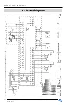
Page 42: ...444 9160 444 9180 442 9020 E 219 GB Issue 1 42 13 Electrical diagrams ...
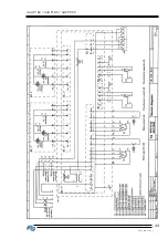
Page 43: ...444 9160 444 9180 442 9020 43 E 219 GB Issue 1 ...
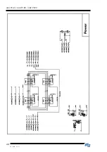
Page 44: ...444 9160 444 9180 442 9020 E 219 GB Issue 1 44 ...
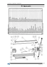
Page 45: ...444 9160 444 9180 442 9020 45 E 219 GB Issue 1 14 Spare parts ...
Page 46: ...444 9160 444 9180 442 9020 E 219 GB Issue 1 46 ...
Page 47: ...444 9160 444 9180 442 9020 47 E 219 GB Issue 1 ...
Page 48: ...444 9160 444 9180 442 9020 E 219 GB Issue 1 48 ...
Page 49: ...444 9160 444 9180 442 9020 49 E 219 GB Issue 1 ...
Page 50: ...444 9160 444 9180 442 9020 E 219 GB Issue 1 50 ...
Page 51: ...444 9160 444 9180 442 9020 51 E 219 GB Issue 1 ...
Page 52: ...444 9160 444 9180 442 9020 E 219 GB Issue 1 52 ...
Page 53: ...444 9160 444 9180 442 9020 53 E 219 GB Issue 1 ...
Page 54: ...444 9160 444 9180 442 9020 E 219 GB Issue 1 54 ...
Page 55: ...444 9160 444 9180 442 9020 55 E 219 GB Issue 1 ...
Page 56: ...444 9160 444 9180 442 9020 E 219 GB Issue 1 56 ...
Page 57: ...444 9160 444 9180 442 9020 57 E 219 GB Issue 1 ...
Page 58: ...444 9160 444 9180 442 9020 E 219 GB Issue 1 58 ...
Page 59: ...444 9160 444 9180 442 9020 59 E 219 GB Issue 1 ...
Page 60: ...444 9160 444 9180 442 9020 E 219 GB Issue 1 60 ...
Page 70: ...444 9160 444 9180 442 9020 E 219 GB Issue 1 70 ...
Page 71: ...444 9160 444 9180 442 9020 71 E 219 GB Issue 1 ...


