background image

www.fmiproducts.com

125566-01A

30

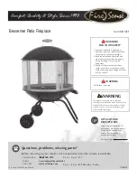
Figure 62 - Correct Pilot Flame Pattern

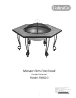
Figure 63 - Incorrect Pilot Flame Pattern

Pilot Burner

Thermocouple

Thermocouple

Pilot Burner

inSPeCtinG bUrnerS

Check pilot flame pattern and burner flame 

patterns often.

PILOT FLAME PATTERN

Figure 62 shows a correct pilot flame pattern. 

Figure 63 shows an incorrect pilot flame pat

-

tern. The incorrect pilot flame is not touching 

the thermocouple. This will cause the thermo-

couple to cool. When the thermocouple cools, 

the heater will shut down.

If pilot flame pattern is incorrect, as shown 

in Figure 63

•  turn heater off (see To Turn Off Gas to Ap

-

pliance

, page 27

•  see 

Troubleshooting

, page 33

Note: The pilot flame on natural gas units will 

have a slight curve, but flame should be blue 

and have no yellow or orange color.

CleaninG and maintenanCe

  WARNING:  Turn  off  heater 

and let cool before cleaning.

  CAUTION:  You  must  keep 

control  areas,  burners  and 

circulating  air  passageways  of 

heater clean. Inspect these areas 

of heater before each use. Have 

heater inspected yearly by a quali

-

fied service person. Heater may 

need more frequent cleaning due 

to excessive lint from carpeting, 

pet hair, bedding material, etc.

 WARNING: Failure to keep 

the  primary  air  opening(s)  of 

the burner(s) clean may result in 

sooting and property damage.

BURNER INjECTOR HOLDER AND 

PILOT AIR INLET HOLE

The primary air inlet holes allow the proper 

amount of air to mix with the gas. This provides 

a clean burning flame. Keep these holes clear 

of dust, dirt, lint and pet hair. Clean these air in

-

let holes prior to each heating season. Blocked 

air holes will create soot. We recommend that 

you clean the unit every three months during 

operation and have heater inspected yearly by 

a qualified service person. 

We also recommend that you keep the burner 

tube and pilot assembly clean and free of dust 

and dirt. To clean these parts we recommend 

using compressed air no greater than 30 PSI. 

Your local computer store, hardware store or 

home center may carry compressed air in a 

can. If using compressed air in a can, please 

follow the directions on the can. If you don’t 

follow directions on the can, you could dam

-

age the pilot assembly.

1.  Shut off unit, including pilot. Allow unit to 

cool for at least thirty minutes.

2.  Inspect burner, pilot and primary air inlet 

holes on injector holder for dust and dirt 

(see Figure 65).

3.  Blow air through the ports/slots and holes 

in the burner.

4.  Check  injector  holder  located  at  end  of 

burner  tube  again.  Remove  any  large 

particles of dust, dirt, lint or pet hair with 

a soft cloth or vacuum cleaner nozzle.

5.  Blow air into the primary air holes on the 

injector holder.

6.  In case any large clumps of dust have now 

been pushed into the burner repeat steps 

3 and 4.

Summary of Contents for LTF18-MM

Page 1: ...rgassupplierfromaneighbor s phone Follow the gas supplier s instructions If you cannot reach your gas supplier call the fire department Installation and service must be performed by a quali fied installer service agency or the gas supplier INSTALLER Leave this manual with the appliance CONSUMER Retain this manual for future reference Variable Remote Control BURNER SYSTEM Models TF18NR PV TF2430NR ...

Page 2: ... heat er It uses air oxygen from the room in which it is installed Provisions for adequate combustion and ventilation air must be provided Refer to Air for Combustion and Ven tilation section on page 6 of this manual This appliance may be in stalled in an aftermarket permanently located manufactured mobile home where not prohib ited by local codes This appliance is only for use with the type of ga...

Page 3: ...teschemicals known to the state of California to cause cancer or birth defects or other reproductive harm IMPORTANT Read this owner s manualcarefullyandcompletely before trying to assemble op erate or service this fireplace Improper use of this fireplace can cause serious injury or death from burns fire explo sion electricalshockandcarbon monoxide poisoning DANGER Carbonmonoxide poisoning may lead...

Page 4: ...ent the creation of soot follow the instructions in Cleaning and Maintenance page 30 9 Before using furniture polish wax carpet cleaner or similar products turn heater off If heated thevaporsfromtheseproductsmay create a white powder residue within burner box or on adjacent walls and furniture 10 This heater needs fresh outside air ven tilation to run properly This heater has an Oxygen Depletion S...

Page 5: ...l local codes In the absence of local codes use the latest edition of The National Fuel Gas Code ANSI Z223 1 NFPA 54 Available from American National Standards Institute Inc 1430 Broadway New York NY 10018 National Fire Protection Association Inc Batterymarch Park Quincy MA 02269 CAUTION Donotremovethe data plates from the grate as sembly The data plates contain important warranty and safety infor...

Page 6: ...Fresh air must enter your home All fuel burning ap pliances need fresh air for proper combustion and ventilation Exhaust fans fireplaces clothes dryers and fuel burning appliances draw air from the house to operate You must provide adequate fresh air for these appliances This will insure proper venting of vented fuel burning appliances PROVIDING ADEQUATE VENTILATION The following are excerpts from...

Page 7: ...Btu Hr the space can support _________ volume of space x 20 Maxi mum Btu Hr the space can support Example 2560 cu ft volume of space x 20 51 200 maximum Btu Hr the space can support 3 Add the Btu Hr of all fuel burning appliances in the space Vent free fireplace ___________ Btu Hr Gas water heater ___________ Btu Hr Gas furnace ___________ Btu Hr Vented gas heater ___________ Btu Hr Gas fireplace ...

Page 8: ...Crawl Space To Attic WARNING Iftheareainwhich theheatermaybeoperateddoes notmeettherequiredvolumefor indoorcombustionair combus tion and ventilation air shall be provided by one of the methods described in the National Fuel GasCode ANSIZ223 1 NFPA54 theInternationalFuelGasCode or applicable local codes VENTILATION AIR Ventilation Air From Inside Building This fresh air would come from an adjoining...

Page 9: ...heater WARNING This appliance is equipped for either natural gas or propane LP gas but not both Gas type is indicated on the rat ingplate Fieldconversionisnot permitted NOTICE Thisheater isintended for use as supplemental heat Use this heater along with your primary heating system Do not install this heater as your pri mary heat source If you have a centralheatingsystem youmay run system s circula...

Page 10: ...ce hood accessory 24 and 30 Models Only See Figure 5 for minimum clearances LOG SIZING REQUIREMENTS Log Size Minimum Firebox Size Height Depth Front Width Rear Width 18 20 14 28 20 24 20 14 32 22 30 20 14 40 30 Carefully follow the instructions below This will ensure safe installation into a masonry UL127 listed manufactured fireplace or listed vent free firebox Minimum Clearances For Side Combust...

Page 11: ...od Minimum Non Combustible Material Minimum Non Combustible Material Height Distances to Underside of Mantel Top of Fireplace Opening Underside of Mantel Shelf 12 8 A 18 14 20 17 22 19 24 20 All minimum distances are in inches Log Set 24 30 Models 18 Model 2 1 2 6 8 10 Mantel Shelf Minimum Noncombustible Material 8 Min 12 15 18 Log Sets 18 24 30 Models 20 2 1 2 6 8 10 12 Distances to Underside of ...

Page 12: ...reads of the 1 2 NPT side of gas fitting elbow provided and connect to inlet side of gas control Remove gas fitting from flexible gas hose provided before connecting to elbow see Figure 10 14 Min Combustible Material Noncombustible Material Figure 8 Minimum Fireplace Clearances If Installed at Floor Level Hearth 5 Min Combustible Material Figure 9 Minimum Fireplace Clearances Above Combustible Flo...

Page 13: ...Thread inlet connection to the pressure regulator WARNING A qualified ser vicepersonmustconnectheater to gas supply Follow all local codes CAUTION Never connect propane LP fireplace directly to the propane LP supply This heaterrequiresanexternalregu lator not supplied Install the external regulator between the heater and propane LP supply WARNING Never connect natural gas fireplace to private non ...

Page 14: ...ial requirements for locating equipment shutoff valve to fireplaces Apply pipe joint sealant lightly to male NPT threads This will prevent excess sealant from going into pipe Excess sealant in pipe could result in clogged heater valves WARNING Use pipe joint sealant that is resistant to liquid petroleum LP gas Propane LP Supply Tank External Regulator with Vent Pointing Down Figure 12 External Reg...

Page 15: ...ze supply piping system by either opening propane LP supply tank valve for propane LP gas or opening main gas valve located on or near gas meter for natural gas or using compressed air 4 Check all joints of gas supply piping system Apply noncorrosive leak detection fluid to all joints Bubbles forming show a leak 5 Correct all leaks at once 6 Reconnect heater and equipment shutoff valve to gas supp...

Page 16: ...r WARNING Make sure your selector switch is in OFF posi tion before installing or chang ing batteries in your hand held remote or receiver Hand Held Remote Control The hand held remote control uses 3 AAA batteries not included To install batteries 1 Remove battery housing cover from back of hand held remote see Figure 17 2 Install or replace batteries 3 Replace battery housing cover When batteries...

Page 17: ... any log With heater set to Hi check to see if flames contact any log If so reposition logs according to log installation instructions in this manual Flames contacting logs will create soot LTF 18 24 30 SO SERIES LOG PLACEMENT It is very important to install these logs exactly as instructed Do not modify logs Only use logs supplied with heater or as identified for use with the heater as shown in F...

Page 18: ...og 3 and square hole in log 5 with square peg on log 1 see Figure 24 6 Place top middle log 6 onto rear log 1 and front log 3 Match square peg on bottom of log 6 with square hole on log 4 and round hole on log 6 with peg on log 1 see Figure 25 2 3 7 Place top right log 7 onto top middle log 6 and front log 3 matching peg on bottom of top right log 7 with hole on top middle log 6 and hole in top ri...

Page 19: ...log is marked with a reference num ber See page 41 for reference numbers detail Place the rear log 1 on base assembly 1 as shown in Figure 28 Log will fit over right end of burner and rest in middle of U burner Place the middle log 2 in front of U 2 burner and against the edges of plate as shown in Figure 29 Figure 27 Correct LTF 18 24 30 SO EMC Log Placement 18 Models 24 Models 30 Models Installa...

Page 20: ...right log will rest against the front of the middle log The notch in the end of the front right log will fit around the grate bar See Figure 31 Place the left top back log 5 on top of 5 the rear log Match the rectangular projec tion on top of the left side of the rear log with the rectangular hole on the bottom of the left top back log Match the metal pin on the top of the rear log with the round ...

Page 21: ...e 36 Final Assembly LTF 18 24 30 MM LOG PLACEMENT It is very important to install the logs exactly as instructed Do not modify logs Only use logs supplied with heater or as identified for use with the heater as shown in Figure 20 page 17 Each log includes reference numbers formed in the bottom or back of the log The circled number indicates the order it is placed on the burner system The remaining...

Page 22: ...right log 4 will fit around the grate bar See Figure 40 Figure 41 Installing Log 5 Figure 40 Installing Log 4 Figure 39 Installing Log 3 Figure 38 Installing Log 2 2 3 Place the left back top log 5 on top of 4 the rear log 1 Match the rectangular peg on top of the left side of the rear log 1 with the rectangular hole on the bot tom of the left back top log 5 Match the metal pin on the top of the r...

Page 23: ...he right rear chunk log 7 7 Place the front right mid log 8 on top of 7 the front right log 4 as shown in Figure 44 Match the round metal pin on the top of the front right log 4 with the round hole on the bottom of the front right mid log 8 Place the top right log 9 on top of the 8 right rear chunk log 7 and front right mid log 8 as shown in Figure 45 Match the round peg on the top of the right re...

Page 24: ...hunk log 7 as shown in Figure 46 Match the rectangular peg on the top of the right rear chunk log 7 with the rectangular hole on the bottom of the right rear top log 10 10 Place the left top log 11 on top of the left back top log 5 and left top forked log 6 as shown in Figure 47 Match the round peg on the top of the left top forked log 6 with the round hole on the bottom of the top left log 11 and...

Page 25: ... bag Separate pieces of ember material and place on surface of flat burner just behind horizontal ports as shown in Figure 49 Rock Wool placement Place rock wool material on front flat burner in areas away from ports as shown in Figure 50 2 Add lava rock and small decorative logs around base of heater if desired DO NOT place rock or additional logs on front burner or on logs Placing any material o...

Page 26: ...follow these instructions exactly B BEFORE LIGHTING smell all around the appliance area for gas Be sure to smell next to the floor because some gas is heavier than air and will settle on the floor WHAT TO DO IF YOU SMELL GAS Do not try to light any appliance Do not touch any electric switch do not use any phone in your building Immediately call your gas supplier from a neighbor s phone Follow the ...

Page 27: ...FF PRG Figure 52 Remote Selector Switch in ON Position Figure 53 Pilot Natural Propane LP Pilot Burner Ignitor Electrode TO TURN OFF GAS TO APPLIANCE 1 Turn control knob clockwise to the OFF position 2 Set selector switch in the OFF position 3 Close equipment shutoff valve see Figure 14 page 15 MANUAL LIGHTING PROCEDURE 1 Follow steps 1 through 6 under Lighting Instructions page 26 2 Depress contr...

Page 28: ...e temperature in either Fahrenheit or Celsius With remote control off press Thermostat button and Mode button at the same time This will toggle the display from F to C Figure 55 Remote Control Display Fahrenheit to Celsius Figure 56 Hand Held Remote Control ON OFF MODE UP DOWN Arrows THERMOSTAT LCD Display OPERATING REMOTE CONTROL WARNING Fireplace can turn on suddenly Keep away from burner After ...

Page 29: ...emperature bulb graphic on display see Figure 58 Use UP DOWN arrow button to set desired room temperature Control system will cycle fireplace on or off to maintain selected temperature To activate this function press THERMOSTAT button until the word SMART appears to the right of temperature bulb graphic on display Use UP DOWN arrow button to set desired room temperature The control system will cyc...

Page 30: ...ng and property damage Burner Injector Holder and Pilot Air Inlet Hole The primary air inlet holes allow the proper amount of air to mix with the gas This provides a clean burning flame Keep these holes clear of dust dirt lint and pet hair Clean these air in let holes prior to each heating season Blocked air holes will create soot We recommend that you clean the unit every three months during oper...

Page 31: ... inlet hole You may blow through a drinking straw if compressed air is not available Cleaning and Maintenance Continued LOGS If you remove logs for cleaning refer to Installing Logs Embers and Lava Rock page 17 to properly replace logs Replace log s if broken or chipped dime sized or larger main burner Periodically inspect all burner flame holes with heater running All slotted burner flame holes s...

Page 32: ... 14 W C Min 11 W C TF18NV Rating Variable 21 000 30 000 Btu Hr Type Gas Natural Ignition Electronic Manifold Pressure 3 4 W C Inlet Gas Pressure in of water Max 10 5 W C Min 5 W C TF2430NV Rating Variable 28 000 39 000 Btu Hr Type Gas Natural Ignition Electronic Manifold Pressure 3 4 W C Inlet Gas Pressure in of water Max 10 5 W C Min 5 W C Wiring Diagram Black Connectors Receiver To Thermopile Wh...

Page 33: ...n gas lines when in stalled 5 Depleted gas supply pro pane LP only 6 ODS pilot is clogged 7 Gas regulator setting is not correct REMEDY 1 Overlap ember material 1 4 see page 25 1 Reconnect ignitor cable 2 Free ignitor cable if pinched by any metal or tubing Keep ignitor cable dry 3 Replace ignitor cable 4 Replace ignitor 5 Replace pilot assembly 6 Replace pilot assembly 7 Install new alkaline bat ...

Page 34: ... knob pressed in 30 seconds 3 Wait one minute for safety interlock system to reset Repeat ignition operation 4 Fully open equipment shut off valve 5 A Contact local natural or propane LP gas company B Clean ODS pilot see Cleaning and Maintenance page 30 or replace ODS pilot assembly 6 Hand tighten until snug then tighten 1 4 turn more 7 Replace pilot assembly 8 Replace control valve 1 Contact loca...

Page 35: ...ners until air is removed from line Have gas line checked by local natural or propane LP gas company 3 Observe minimum installa tion clearances see pages 9 through 11 4 Clean burners see Clean ing and Maintenance page 30 or replace burner orifice s 1 Turn heater off when us ing furniture polish wax carpet cleaners or similar products 1 Refer to Air for Combustion and Ventilation require ments page...

Page 36: ...ged 1 Gas leak See Warning statement at top of page 2 Control valve or gas control defective 1 Foreign matter between control valve and burner 2 Gas leak See Warning statement at top of page 1 Hand held remote control is too close to heater REMEDY 1 Open window to venti late room Stop using odor causing products while heater is running 2 Refill supply tank propane LP only 3 Locate and correct all ...

Page 37: ...lacement Parts Note Use only original This will protect your warranty coverage for parts replaced under warranty Contact authorized dealers of this product If they can t supply original replacement part s call FMI PRODUCTS LLC at 1 866 328 4537 When calling have ready your name your address model and serial numbers of your heater how heater was malfunctioning purchase date Usually we will ask you ...

Page 38: ...2 4 5 8 9 10 20 18 19 17 13a 12 PARTS AVAILABLE NOT SHOWN 100563 01 Warning Plate 1 103877 01 Lighting Instruction Plate 1 100639 12 Caution Decal 1 101137 02 Hardware Kit 1 GA6060 Lava Rock 1 120466 01 Flextube with Fitting TF models only 1 125071 01 Rockwool Embers 1 125070 01 Platinum Bright Embers Kit 1 099998 01 Fan Switch 1 103284 11 Wire Harness 1 ...

Page 39: ...40 Orifice 0 0635 1 099056 41 Orifice 0 0335 1 099056 47 Orifice 0 066 1 099056 46 Orifice 0 0689 1 14 125019 01 Ignitor Bracket 1 15 111435 01 Electronic Ignitor 1 16 098271 12 Ignitor Cable 1 17 112829 02 Air Shutter 1 18 119795 01 Gasket 1 19 119321 01 Venturi Tube 1 20 097384 01 ODS Nut 2 21 116559 04 Natural Gas Air Shutter 1 116559 03 Propane LP Gas Air Shutter 1 22 124933 01 Holder Orifice ...

Page 40: ...ht Log 3 1 4 125052 05 125052 06 125052 07 Front Log 4 1 5 120954 05 125052 09 125052 09 Top Left Log 5 1 6 120954 06 120954 06 120954 06 Top Middle Log 6 1 7 120954 07 120954 07 120954 07 Top Right Log 7 1 8 121079 01 121079 01 121079 01 Switch Log 1 Parts Log Sets for Models LTF18 SO LTF14 SO LTF30 SO This list contains replaceable parts used in your heater When ordering parts follow the instruc...

Page 41: ...r Crossover Log 8 1 9 125538 01 125538 01 125538 01 Switch Log 1 Parts Log Sets for Models ltf18 mo ltf24 mo ltf30 mo This list contains replaceable parts used in your heater When ordering parts follow the instructions listed under Replacement Parts on page 37 of this manual 2 6 3 4 9 1 7 8 5 Each log includes reference numbers formed in the bottom or back of the log The circled number indicates t...

Page 42: ...65 01 Middle Log 2 1 3 125335 03 125336 03 125337 03 Front Left Log 3 1 4 125563 02 125564 02 125565 02 Front Right Log 4 1 5 125563 03 125564 03 125564 03 Left Top Back Log 5 1 6 125563 04 125564 04 125565 04 Left Top Forked Log 6 1 7 125563 05 125564 05 125565 05 Right Rear Chunk Log 7 1 8 125563 06 125564 06 125564 06 Front Right Middle Log 8 1 9 125563 07 125564 07 125565 07 Top RIght Log 9 1 ...

Page 43: ..._______________________________ ______________________________________________________ ______________________________________________________ ______________________________________________________ ______________________________________________________ ______________________________________________________ ______________________________________________________ ______________________________________...

Page 44: ...his product and or FMI PRODUCTS LLC who will provide original factory Failure to use original factory voids this warranty Travel handling transportation diagnostic material labor and incidental costs associated with warranty repairs unless expressly covered by this warranty are not reimbursable under this warranty and are the responsibility of the owner Excluded from this warranty are products or ...

Reviews: