
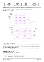


M
ODEL
SDP100 V
ERSION
V_1.00
P
REPARED BY
H/W
D
ATE
25/05/2007
S
UBJECT
T
ECHNICAL
M
ANUAL
P
AGE
38/70
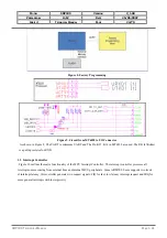
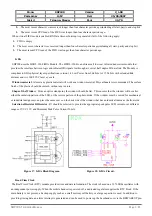
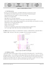
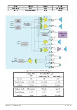
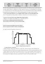
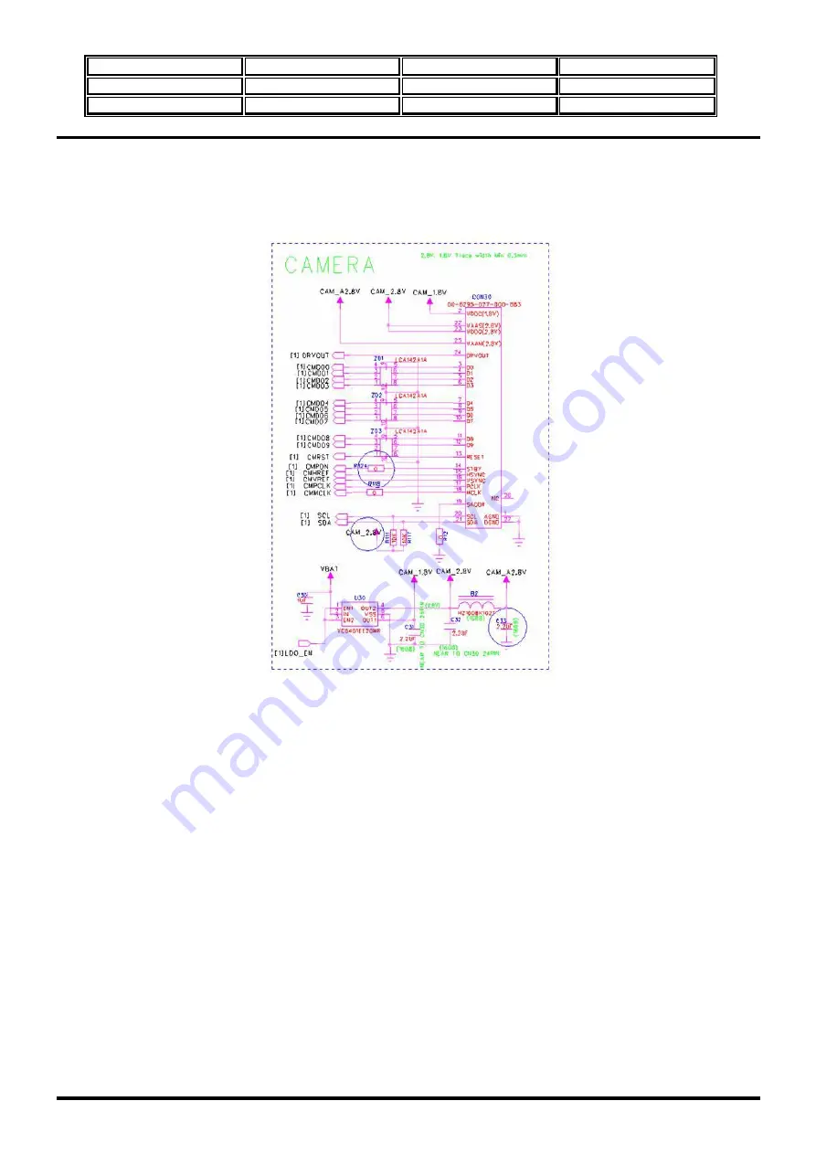
In SDP100
, Camera Sensors can be selected by BB processor. If MT6228 is used, The Camera Module can be used
3Mpixels sensor from Micron
(MT97012).
, The 2 Power supplies are used(2.8V, 1.8V) and 10bit data interface. The I2C
signals need a pull up resistor 10Kohm. The CMMCLK is a 24Mhz and this is strong signal. So, The R32 and C37 used for
EMI. Or Can be used the 600ohm bead at 100Mhz.
Figure 26. Camera Sensor Interface circuit.
6.6
TV Controller
MT6228 supports NTSC/PAL interlaced TV format. The display function includes two components: a TV controller
and a TV encoder. The main functions of the TV controller are as follows:
1.
Fetch the TV frame buffer.
In video playback mode, the source is from the video codec buffer in YUV420 format.
In this mode, the TV controller and MPEG4 decoder can also communicate to achieve the best performance. In image
playback mode, the source is in RGB565 format. In this mode, still images can be displayed. The LCM controller can
direct the image path to the TV controller. When the LCM controller sends frames to the frame buffer as it does for the
LCD display, the TV controller retrieves the frames for display.
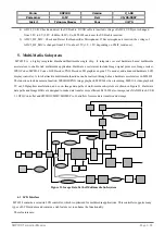
2.
Scale the frame size to fit the TV size
. MT6228 adopts bilinear interpolation in both horizontal and vertical
dimension to scale up the frame. The user can adjust both the location and the size to achieve a suitable appearance.
In NTSC mode, the ideal display area is 720(W) x 480(H), but the actual display area depends on the TV set.
In PAL mode, the ideal display area is 720(W) x 576(H); the actual display area also depends on the TV set. TV frame
updates consume a lot of bandwidth. For interlaced system, one frame contains 2 fields. In NTSC mode, the field update
rate is 59.94 frames per second (fps); the field update rate in PAL mode is 50 fps. Performance is bound by the size of
the source image. The larger the image size, the higher the bandwidth required to support the TV display. The controller
SDP100
T
ECHNICAL
M
ANUAL
Page 3.38