background image

Thermal Imager Camera 

Internal ThermoView® Web-Server Application 


13 

6. Internal ThermoView

®

 Web-Server Application 


The ThermoView® imager is equipped with an onboard web-server. Several informations are 

available by call and will be displayed in specific screen domains on an attached computer 

monitor.  Furthermore,  several  settings  can  be  initiated  and  transferred  to  the  imager.  It  is 

possible to display or set the device IP address, to modify the focus of the infrared camera or 

to upload a new firmware. Of course, there are two screen domains for displaying the infrared 

camera image on the upper screen domain and the visible light camera image on the lower 

screen domain.  


Figure 11: Screenshot of the ThermoView® onboard web-server application 


Summary of Contents for ThermoView Series

Page 1: ...amera Users Manual PN 59802 May 2018 Rev 1 0 05 2018 2018 Fluke Process Instruments All rights reserved Printed in Germany Specifications subject to change without notice All product names are tradema...

Page 2: ...SEQUENTIAL DAMAGES WHETHER IN CONTRACT TORT OR OTHERWISE Software Warranty The manufacturer does not warrant that the software described herein will function properly in every hardware and software en...

Page 3: ...subject to change without notice The device complies with the requirements of the European Directives EC Directive 2014 30 EU EMC EC Directive 2011 65 EU RoHS II Electromagnetic Compatibility Applies...

Page 4: ...rmoView Web Server Application 13 7 Accessories 14 7 1 Available electrical accessories for ThermoView cameras 14 7 1 1 Power supply cable 80 C max 7 5m 25ft A CB LT PS 07 14 7 1 2 Power supply cable...

Page 5: ...kit for several In Outputs A CON BASICKIT 28 7 2 Available mechanical accessories for ThermoView cameras 29 7 2 1 Air purge collar A TV AP 29 7 2 2 Air purge collar including water cooling accessory A...

Page 6: ...iv List of Tables Title Page Table 1 General Symbols 2 Table 2 Available Models 3 Table 3 Typical Emissivity Values Non Metals 40 Table 4 Typical Emissivity Values Metals 42...

Page 7: ...DIN 24V 19 Figure 17 Ethernet cable 25 m 82 ft with RJ45 connectors on both ends 19 Figure 18 Fiber Optic to Ethernet Converter 6 RJ45 2 Multi Mode FO ports 20 Figure 19 Fiber Optic Cable Multi Mode...

Page 8: ...perating instructions is necessary to ensure the expected results Unacceptable Operation The instrument should not be used for medical diagnosis Replacement Parts and Accessories Use only original par...

Page 9: ...tage Risk of electrical shock Helpful information regarding the optimal use of the instrument Earth ground Protective ground Fuse Normally open NO relay Normally closed NC relay Switch or relay contac...

Page 10: ...GigE Vision network interface which supports the PoE standard IEEE 802 3at Power over Ethernet max 25 4 W 1 Gbit data Such a high speed interface allows an easy networking and power supply over long d...

Page 11: ...a Model 3 6 as sensor array resolution identifier Unique ThermoView Series Sub item Identifier Unique ThermoView Series Identifier Frame rate ident 0 1 IR camera frame rate 60Hz fps Fixed defined T fo...

Page 12: ...b Housing Material Aluminum bright dipped anodized clear coated Dimensions 83 mm 3 27 in x 83 mm 3 27 in x 154 mm 6 0 in Width x Height x Length Sighting Frame rate 9 fps or 60 fps for thermal camera...

Page 13: ...On Lens 4 x Telephoto Add On Lens Macro TV43 horiz x vert TV46 horiz x vert 34 x 25 5 34 x 25 5 45 x 34 45 x 34 17 x 12 7 17 x 12 7 8 5 x 6 3 8 5 x 6 3 7 8 x 4 1 mm 0 31 x 0 16 in 11 x 8 2 mm 0 43 x...

Page 14: ...following ThermoView Series IR Camera User Manual and Quickstart are stored in the camera memory Metal sealing connector caps for GigE connector and power connector Printed version of Safety Data She...

Page 15: ...terial Determine the emissivity of the target object as described in the appendix When measuring materials with low emissivity the results could be effected by interfering infrared radiation from back...

Page 16: ...the field of view Figure 6 Field of View for the Camera 5 4 1 Spot size IFOV calculation of aperture angle for different lens types It is important that the ThermoView camera is mounted at a distance...

Page 17: ...accuracy Avoiding or removing physical mounting limitations and obstructions in the camera s optical path may also be required 5 7 Cable Connections Before connecting and disconnecting any connector...

Page 18: ...to the camera 2 Tighten the outer nut of the female connector 3 Supply the open pig tail ends with power 12VDC 26VDC Take care about the right polarity and connect the brown wire to Ground and the whi...

Page 19: ...liant one without changing the software application The advantages of the GigE interface are High data rates of up to 125 MB s Reuseability of existing Ethernet structure Cable length up to 100 m 328...

Page 20: ...an attached computer monitor Furthermore several settings can be initiated and transferred to the imager It is possible to display or set the device IP address to modify the focus of the infrared came...

Page 21: ...ctors A CON FO RJ45 FiberOptic RJ45 Converter A CB FO 150 Fiber Optic Cable 150 m 492 ft A CB FO 300 Fiber Optic Cable 300 m 984 ft A CON SW 4 Port Gigabit Ethernet Switch A CB LT RJ45 03 Ethernet cab...

Page 22: ...th differs and is 50m 160ft instead of 7 5m 25ft 7 1 4 Ethernet cable 80 C max 7 5m 25ft A CB LT M12 W08 07 The Gigabit Ethernet cable comes with an eight pin male M12 connector assigned to the camera...

Page 23: ...wer applications The device generates up to 30W and enables remote power for a new range of applications It complies with the IEEE 802 3at PoE standard and is backward compatible with IEEE802 3af It c...

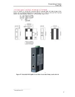
Page 24: ...le port industrial DIN rail mounted IEEE 802 3af at Gigabit PoE Injector with an extended temperature range between 40 C 40 F to 75 C 167 F The PoE injector can power attached devices e g IP cameras o...

Page 25: ...ThermoView Series Users Manual 18 Specifications...

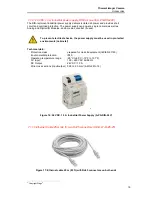
Page 26: ...shocks the power supply must be used in protected environments cabinets Technical data Protection class prepared for class II equipment IEC EN 61140 Environmental protection IP20 Operating temperature...

Page 27: ...verter A CON FO RJ45 The A CON FO RJ45 is an industrial DIN rail mounted unmanaged Ethernet switch with 6 RJ45 GBit Ethernet ports and 2 Multi Mode GBit Fiber Optic ports 4 Figure 18 Fiber Optic to Et...

Page 28: ...Thermal Imager Camera Accessories 21 Specifications...

Page 29: ...Fiber Optic Cable 150 m 492 ft A CB FO 150 Just the supplied cable length differs and is 300 m 984 ft instead of 150 m 492 ft 7 1 14 4 Port Gigabit Ethernet Switch A CON SW The A CON SW is a 4 port in...

Page 30: ...SFP Fiber Ports Features All Gigabit Ethernet ports for 4 Copper and 2 SFP Back plane Switching Fabric 12Gbps Embedded 4 ports PoE inject function Provide 30 W at 55 V power output Redundant Power Des...

Page 31: ...ThermoView Series Users Manual 24 7 1 15 Ethernet cable short for Junction Box A CB LT RJ45 03 Figure 21 Ethernet patch cable short 0 3m 1ft...

Page 32: ...WAGO module 750 1406 Document title I O Module System for Infrared Linescanners and Thermal Imagers 7 1 17 Digital Out 16 each A CON 16DO 7 Figure 23 16 Channel Digital Output Module A CON 16DO Pleas...

Page 33: ...is preset to 0 20mA Document title I O Module System for Infrared Linescanners and Thermal Imagers 7 1 19 Analog Current Out 2 loops 4 20mA A CON 2AOC4 9 Figure 25 2 Analog Current Loop Output 4 20mA...

Page 34: ...0 513 Document title I O Module System for Infrared Linescanners and Thermal Imagers 7 1 21 Passive Current Isolator A CON 2A ISO 11 Figure 27 2 Channel Passive Current Isolator Module A CON 2A ISO Pl...

Page 35: ...refer to the Fluke Process Instruments document below to get technical details and installation instructions for the WAGO module 750 352 750 602 750 600 Document title I O Module System for Infrared L...

Page 36: ...P WC Air purge collar including water cooling accessory A TV WC Protective enclosure water cooled air purged A TV ENC Outdoor Enclosure A TV MB Mounting Base A TV SB Swivel Bracket A TV CC Carrying Ca...

Page 37: ...accessory A TV AP WC Max ambient temperature 140 C 284 F Medium ambient temperatur 20 C 68 F Recommended water flow rate 1 6 l min 0 42 gpm Air flow rate 30 60 l min 7 925 15 85 gpm Air pressure 5 bar...

Page 38: ...ThermoView imager needs to be installed in dirty and hot environments a protective enclosure with water cooling and air purge fittings is needed to guarantee the protection Figure 33 Front rear view o...

Page 39: ...e outer surface of the window For proper use it is always advisable to filter the compressed air with a dedicated filter that is equipped with a gauge pressure regulator For proper installation it is...

Page 40: ...e Using Ethernet and power cables that have been passed through cable glands on rear flange Install cables onto camera as shown turn camera on if needed Place conduction plate onto inside surface of e...

Page 41: ...nium window Double thermostat control heater Cable glands Environment Rating IP66 IP67 EN60529 with cable glands Max Temperature 30 to 50 C 22 to 122 F Electrical Double heater 115 230 VAC 80 W Mechan...

Page 42: ...rn past after contacting curved washer and slide camera forward Secure ground cable to camera as shown color of cable ring terminals used for display only from camera to internal rail screw with tooth...

Page 43: ...ghten rear cover 3x screws then tighten 2x set screws on outer slide as shown Slide camera forward if needed and ensure that camera conduction plate contacts inside surface of enclosure in order to en...

Page 44: ...View imager in an easy way to any kind of fixture It is mainly foreseen to fix the ThermoView imager to swiveling brackets or tripods For the fixture to tripods or swivel brackets the mounting base ha...

Page 45: ...orientation you can pitch 0 90 and swivel 0 360 the imager sighting axis The base has a single control knob and a split ball lock to hold the specific head mount firmly in place Base features Circle...

Page 46: ...nol Apply one of the above to the lens Wipe gently with a soft clean cloth until you see colors on the surface then allow to air dry Do not wipe the surface dry this may scratch the surface If silicon...

Page 47: ...8 Carborundum 0 9 Ceramic 0 95 Clay 0 95 Concrete 0 95 Cloth 0 95 Glass Plate 0 85 Gob Gravel 0 95 Gypsum 0 8 0 95 Ice 0 98 Limestone 0 98 Paint non al 0 9 0 95 Paper any color 0 95 Plastic opaque at...

Page 48: ...1 Oxidized 0 4 0 8 Gold 0 01 0 1 Haynes Alloy 0 3 0 8 Inconel Oxidized 0 7 0 95 Sandblasted 0 3 0 6 Electropolished 0 15 Iron Oxidized 0 5 0 9 Unoxidized 0 05 0 2 Rusted 0 5 0 7 Molten Iron Cast Oxid...

Page 49: ...2 Steel Cold Rolled 0 7 0 9 Ground Sheet 0 4 0 6 Polished Sheet 0 1 Molten Oxidized 0 7 0 9 Stainless 0 1 0 8 Tin Unoxidized 0 05 Titanium Polished 0 05 0 2 Oxidized 0 5 0 6 Tungsten 0 03 Polished 0 0...

Reviews: