


MP
Series
Users Manual, Rev. 1.0, Apr 2021
38
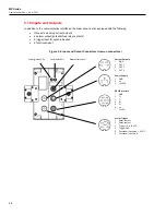
5.10 Inputs and Outputs
In addition to the communication interfaces, the linescanner is also equipped with the following:
•
three active analog current outputs
•
an alarm output (potential-free relay contacts)
•
a trigger input for synchronization
•
a functional input
Figure 5-4: Input and Output Connectors (view on connectors)
Power (green LED)
Laser (red LED)
Ethernet Interface
Current Outputs
1
IGND
2
OUT 1
3
OUT 2
4
OUT 3
Power Supply
1
GND
2
n.c.
3
+24 VDC
RS485 Interface
1
GND
2
T+
3
T-
4
R+
5
R-
6
n.c.
7
12 VDC
Alarm, Trigger
1
Relay contact
2
Relay contact
3
T 5 to 24 VDC
4
Trigger GND
5
Functional Input: max. + 5 VDC
6
Functional Input: GND


