


12
of
18
LC900007
Rev
A2
APPLICATION
EXAMPLES
(cont.)
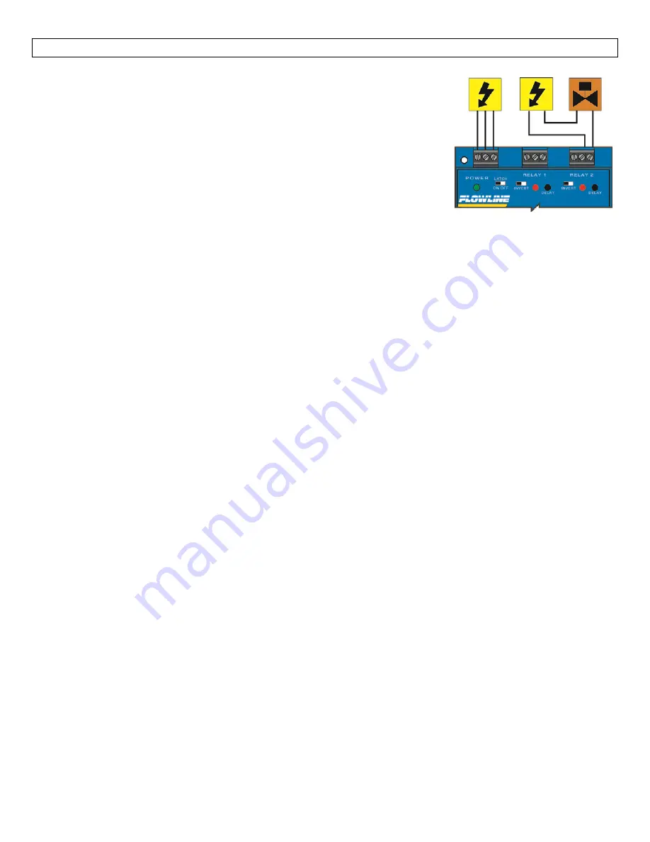
Step
Seven
Automatic
Fill:
This
system
consists
of
a
tank
with
a
valve
controlled
by
the
LC52.
At
a
low
set
point,
the
valve
opens,
filling
the
tank.
At
the
high
set
point,
the
valve
closes.
Part
of
a
proper
fail
‐
safe
design
for
this
particular
system
is
that
if
power
is
lost
to
the
controller
for
any
reason,
the
valve
filling
the
tank
must
close.
Therefore,
we
connect
the
valve
to
the
NO
side
of
the
relay.
When
the
relay
is
energized,
the
valve
will
open
and
fill
the
tank.
The
relay
indicator
will
correspond
directly
to
the
Open/Close
status
of
the
valve.
NOTE:
If
the
device’s
load
exceeds
the
rating
of
the
controller’s
relay,
a
stepper
relay
of
higher
capacity
must
be
used
as
part
of
the
system
design.
Determining
the
settings
of
LATCH
and
INVERT:
This
is
the
way
the
system
must
operate:
When
the
liquid
level
is
below
the
low
relay
set
point,
the
valve
should
open,
starting
to
fill
the
tank.
When
the
liquid
is
above
the
low
relay
set
point,
the
valve
will
remain
open.
When
the
liquid
reaches
the
high
relay
set
point,
the
valve
should
close.
Latch:
In
any
2
‐
setpoint
relay
configuration,
LATCH
must
be
ON.
Invert:
Referring
to
the
logic
chart
in
Step
Nine,
we
look
for
the
setting
that
will
de
‐
energize
the
relay
(valve
close)
when
both
relay
set
points
are
wet.
In
this
system,
Invert
should
be
ON.
Automatic
Empty:
In
the
same
manner,
the
controller
can
be
used
to
automatically
empty
a
tank
with
just
a
change
to
the
setting
of
the
INVERT
switch:
•
The
valve
is
still
connected
to
the
NO
side
of
the
relay
to
allow
for
a
power
failure
fail
‐
safe
condition.
•
The
normal
state
of
the
valve
is
closed.
In
this
state,
we
want
the
relay
to
be
energized
at
the
high
relay
set
point
(opening
valve
to
drain
tank).
The
relay
will
de
‐
energize
at
the
low
relay
set
point
(closing
valve).
Note:
A
fail
‐
safe
design
is
important.
If
the
tank
is
being
passively
filled,
and
a
valve
must
be
used
to
actively
empty
it,
a
power
failure
to
either
the
controller
or
the
pump
circuits
will
cause
overflow.