Rev
A2
LC900007
1
of
18
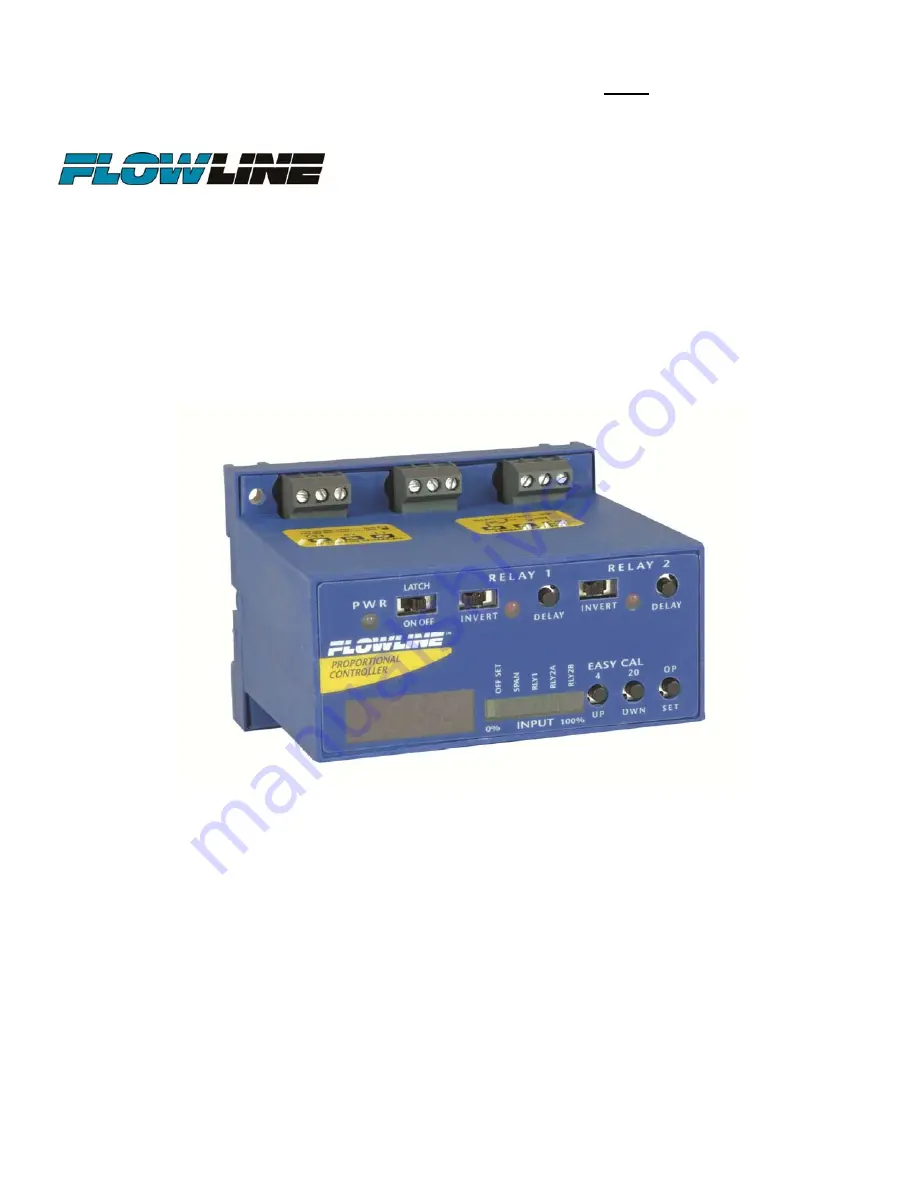
DataPoint
Continuous
Relay
Controller
LC52
Series
Manual
CALL TOLL FREE 877-742-2878 FOR SALES AND SUPPORT. CLICK HERE TO RETURN TO WEBSITE
Page 1: ...Rev A2 LC900007 1 of 18 DataPoint Continuous Relay Controller LC52 Series Manual CALL TOLL FREE 877 742 2878 FOR SALES AND SUPPORT CLICK HERE TO RETURN TO WEBSITE ...
Page 2: ...its Fail Safe relay control of pumps valves or alarms with a 0 15 to 60 second delay Polypropylene enclosure can be DIN rail mounted or back panel mounted Easy setup with push button calibration for display and relay settings AC powered Table of Contents Specifications 3 Dimensions 3 Safety Precautions 4 Make a Fail Safe System 5 Components 5 Installation 5 Getting Started 6 Features of the Single...
Page 3: ...VDC 25mA primary 28 VDC 50mA secondary Contact type 1 SPDT 1 Latched SPDT Contact rating 250 VAC 12A Hp Contact output Selectable NO or NC Contact latch ON or OFF Contact configuration 1 High or low level alarm 2 High and low level alarm 3 Automatic fill or empty 4 Automatic fill or empty with alarm Contact delay 0 15 60 seconds Fail safety Power fail safe Repeater output 4 20 mA 12 36 VDC Ambient...
Page 4: ...al electrical codes Flammable or Explosive Applications The LC52 series continuous relay controllers should not be used with explosive or flammable liquids which require an intrinsically safe or explosion proof rating If you are unsure of the suitability of a controller for your installation consult your Flowline representative for further information Install In a Dry Location The controller housi...
Page 5: ...contact so that it will not complete the circuit when it should In critical applications redundant backup systems and alarms must be used in addition to the primary system Such backup systems should use different sensor technologies where possible While this manual offers some examples and suggestions to help explain the operation of FLOWLINE products such examples are for information only and are...
Page 6: ...lay from 0 15 to 60 seconds can be set before the relay responds to the sensor input Typical applications for single input relays are high level or low level switch alarm operations opening a drain valve whenever liquid level rises to a set point and over flow protection turning off a pump or sounding an alarm when a high level is reached Features of a Latching Relay automatic fill or empty The la...
Page 7: ... amps for reactive loads the current must be derated or protection circuits used When the red LED is ON and the relay is in the energized state the NO terminal will be closed and the NC terminal will be open 5 Invert switch This switch reverses the logic of the relay control in response to the switch es conditions that used to energize the relay will now de energize the relay and vice versa 6 Time...
Page 8: ...quick review of wiring the LC52 series to common 4 20 mA transmitters EchoSonic II LU23 LU27 LU28 LU29 series EchoPod DL10 DL14 DL24 DL34 series Sourcing mode Factory Setting EchoSpan LU80 LU81 LU83 LU84 series Sourcing Mode Factory Setting Echotouch LU30 5004 and LU30 5064 only Sourcing Mode Factory Setting Echotouch LU30 5003 and LU30 5063 only Sinking mode internal jumper must be changed DeltaS...
Page 9: ...urcing to sinking remove jumper from JWA and place on JWB The LC52 is shipped from the factory in the sourcing mode JWA active 4 Gently return PCB into housing and replace back panel Note Loop powered devices can operate in either the souring or sinking modes Sourcing Mode Sinking Mode No Change Required EchoSonic II LU23 LU27 LU28 LU29 series EchoSpan LU80 LU81 LU83 LU84 series EchoPod DL10 DL14 ...
Page 10: ...uit board PCB from the housing Use caution when removing the PCB 2 Locate jumpers JW1 JW2 and JW3 on the PCB 3 To change from 120 VAC to 240 VAC a Remove the jumpers from JW1 JW2 and add a jumper to JW3 4 To change from 240 VAC to 120 VAC a Remove the jumper from JW3 and add jumpers to JW1 JW2 5 Gently return PCB into housing and replace back panel 120 VAC Jumper Setting 240 VAC Jumper Setting Rel...
Page 11: ...ower supply or some other indicator or backup alarm to warn of a power failure in the alarm circuit In this application the normal status of the relay set point at the bottom of the tank will be wet and the relay will be energized holding the alarm circuit open The relay LED will be ON so for this application Invert should be set to the OFF position High Level Alarm In the same manor this system c...
Page 12: ...hould open starting to fill the tank When the liquid is above the low relay set point the valve will remain open When the liquid reaches the high relay set point the valve should close Latch In any 2 setpoint relay configuration LATCH must be ON Invert Referring to the logic chart in Step Nine we look for the setting that will de energize the relay valve close when both relay set points are wet In...
Page 13: ...bar graph will jump one Green bar to the right next to RLY2A 8 Use UP DWN buttons to change display to the desired RLY2A value 9 Press the SET button again Immediately the LED bar graph will jump one Green bar to the right next to RLY2B 10 Use UP DWN buttons to change display to the desired RLY2B value 11 Press the SET button again Immediately the LED bar graph will return back to it normal operat...
Page 14: ...mpty with latch ON With Latch OFF the relay will only respond to the RLY 2A relay set point RLY 2B will be ignored With Latch OFF the setting for RLY 2B will be ignored All changes to the relay s state will occur from the RLY 2A relay set point Invert OFF Latch OFF RLY 2A RYL 2B Relay Wet Dry No Effect No Effect ON OFF Invert ON Latch OFF RLY 2A RYL 2B Relay Wet Dry No Effect No Effect OFF ON With...
Page 15: ...A Check for loose or open wires between the transmitter and LC52 and check the output of the transmitter Bar Graph shows a single Red bar This indicates a current input greater than 20mA Remove power immediately Check for a short in the wiring between the transmitter and LC52 or for some other power source that is affecting the input loop RLY 2B does not appear Flip Latch switch to ON Relay switch...
Page 16: ...e LC52 1001 OFFSET 0 0 SPAN 60 0 RLY 1 55 0 RLY 2A 50 0 RLY 2B 10 0 The next exercise demonstrates the same inventory control with automatic filling and a high level alarm However the units have been changes from inches to gallons Within the tank 1 50 gallons of liquid The usable range is now 300 gallons of liquid The pump starts filling at 50 gallons of liquid and stops filling at 250 gallons of ...
Page 17: ...C52 1001 OFFSET 16 0 SPAN 56 0 RLY 1 50 0 RLY 2A 20 0 RLY 2B N A The next exercise demonstrates the same inventory control with a high and low level alarm However the units have been changes from inches to gallons Along the straight side of the tank 1 50 gallons of liquid The usable range is now from 50 to 250 gallons of liquid The high level alarm occurs at 220 gallons of liquid The low level ala...
Page 18: ...ocedures outlined above 2 have been subjected to electrical mechanical or chemical damage due to improper accidental or negligent use 3 have been modified or altered 4 anyone other than service personnel authorized by Flowline have attempted to repair 5 have been involved in accidents or natural disasters or 6 are damaged during return shipment to Flowline Flowline reserves the right to unilateral...