


Rev
A2
LC900007
11
of
18
APPLICATION
EXAMPLES
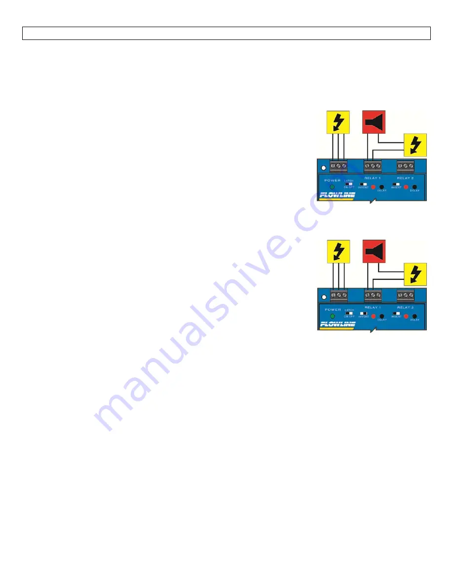
Step
Seven
Low
Level
Alarm:
The
goal
is
to
make
sure
that
the
liquid
level
does
not
fall
below
a
certain
point.
If
it
does,
an
alarm
is
supposed
to
sound,
alerting
the
operator
of
a
low
level
condition.
If
power
is
accidentally
cut
to
the
controller,
the
sensor's
ability
to
notify
the
operator
of
a
low
level
condition
could
be
lost.
The
system
must
alert
the
operator
not
only
to
low
liquid
level,
but
to
controller
power
loss.
To
do
this,
connect
the
hot
lead
of
the
alarm
to
the
NC
side
of
the
relay
terminal
of
the
controller.
If
power
is
lost,
the
relay
will
be
de
‐
energized,
and
the
alarm
will
sound
(if
there
is
still
power
to
the
alarm
circuit
itself).
The
alarm
circuit
should
have
a
non
‐
interruptible
power
supply
or
some
other
indicator
or
backup
alarm
to
warn
of
a
power
failure
in
the
alarm
circuit.
In
this
application,
the
normal
status
of
the
relay
set
point
at
the
bottom
of
the
tank
will
be
wet,
and
the
relay
will
be
energized
holding
the
alarm
circuit
open.
The
relay
LED
will
be
ON,
so
for
this
application,
Invert
should
be
set
to
the
OFF
position.
High
Level
Alarm:
In
the
same
manor,
this
system
can
be
used
to
sound
an
alarm
when
fluid
reaches
a
high
level,
with
just
a
change
in
the
location
of
the
relay
set
point
and
the
setting
of
the
Invert
switch.
The
alarm
is
still
connected
to
the
NC
side
of
the
relay
to
allow
for
a
power
failure
alarm.
The
relay
set
point
is
normally
dry.
In
this
condition,
we
want
the
relay
to
be
energized
so
the
alarm
does
not
sound:
i.e.,
the
Red
relay
LED
should
be
ON
when
alarm
condition
occurs.
So
we
turn
Invert
On.
If
the
fluid
level
rises
to
the
high
relay
set
point,
the
relay
de
‐
energizes,
and
the
alarm
sounds.