background image

010639-X (Rev. H)
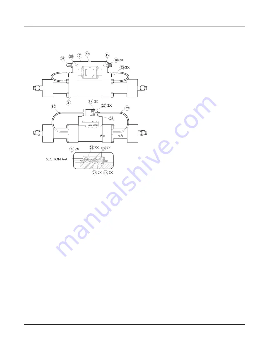
Manifold assembly, mechanical shift

Item Part #

Qty

Description

3

010558-30

1

Intensifier assembly

4

002226-1

2

Actuator pin

7

013403-1

1

Manifold

16

A-0275-014

2

O-ring

17

A-0275-019

2

O-ring

18

A-0636-23

2

Connector

19

A-0638-3

1

Elbow

20

A-0641-6

1

Plug

22

A-0641-7

3

Plug

23

A-1012

2

Spring

24

A-1713

2

Compression spring

26

B-1007-1

2

Actuating plunger

27

B-1611-1

2

Shift pin

28

A-11215

1

Shift valve/pilot valve assy
(C-2743-1, shift valve & 006869-1, pilot valve)

29

C-5461

1

Cable guide assembly, RH

30

C-5462

1

Cable guide assembly, LH

ESL Intensifier

© Flow International Corporation

M-310 | 37

Summary of Contents for ESL INTENSIFIER

Page 1: ...ESL INTENSIFIER M 310 REV G JANUARY 2009...

Page 2: ...made herein nor for any incidental or consequential damage resulting from the use of this material This document contains information protected by copyright No part of this document shall be reproduc...

Page 3: ...ce procedures 12 Intensifier service notes 12 Major parts of the intensifier 13 High pressure water cylinder and seals 14 End cap and check valve 20 Lapping the sealing surfaces 24 Hydraulic oil cylin...

Page 4: ...to personnel CAUTION Highlights an operating or service procedure or condition that can lead to impaired system operation or equipment damage Note Highlights an operating or service procedure or condi...

Page 5: ...are recommended but other manufacturer s equiva lents can be used Mobil DTE Medium or DTE 25 Shell Turbo T 46 Chevron Turbine Oil GST 46 Texaco Regal R O 46 Operating principles The intensifier pump...

Page 6: ...part orders Practice good housekeeping Assign a complete set of service tools to the workstation Maintenance precautions Protect all machined and lapped mating surfaces from damage Carefully work out...

Page 7: ...by a damaged o ring on the check valve body or a damaged high pressure seal whether or not the inten sifier is running Check leakage quantity If seepage is very gradually in creasing has not suddenly...

Page 8: ...vice required to remedy the problem When you encounter a system malfunction 1 Carefully and precisely define the problem 2 On the troubleshooting table locate the symptom that most closely resembles y...

Page 9: ...spool movement on both the pilot and shift valves Inspect spools for defects Hand lap with 600 grit paper If unable to remove defects replace valve 2 Intensifier knocks severely Low inlet water press...

Page 10: ...clearance between plunger and new backup ring must be less than 0 002 inch 0 05 mm Replace if scratched pitted or below tolerance 2 Replace water seals and seal backup ring 8 Water leaking from end c...

Page 11: ...gue Replace HP water cylinder The cylinder has a limited fatigue life and will re quire periodic replacement depending on the application Premature failure is primarily attributed to scratches in the...

Page 12: ...urers Immediately replace all cracked check valve parts and clean up leakage All threaded high pressure connections require a fresh even coating of Blue Lubricant Do not sub stitute another product Cl...

Page 13: ...Major parts of the intensifier Flow International Corporation M 310 13 ESL Intensifier Check valve assembly High pressure cylinder assembly...

Page 14: ...pply water hose at the quick disconnect Using two wrenches disconnect the high pressure water line from the check valve outlet body Loosen the other end and move the tubing out of the way CAUTION Do n...

Page 15: ...N DO NOT grip the cylinder with any sharp toothed tool Surface scratches and gouges will lead to early part failure 7 Remove the cylinder by hand carefully sliding it off the plunger to avoid scoring...

Page 16: ...to the end of the cylin der to remove the seal located in the opposite end Repeat to remove the seal in the other end of the cylinder 13 Remove the seal backup sleeve 14 Carefully clean the high press...

Page 17: ...sed to lubricate the threads it must also be kept dirt free 20 Wipe the inner surface of the seal installation sleeve with white food grade o ring lube and place it into the sleeve guide small ID firs...

Page 18: ...y slight intermittent resistance Note The seal ring is a wear item and must be replaced at every seal change 28 Coat the plunger evenly with a thin layer of white food grade o ring lube 29 Coat the th...

Page 19: ...e end cap higher than 100 ft lb 75 N m is unnecessary and makes disassembly more difficult 34 Using two wrenches connect the high pressure tubing at both ends and connect the supply wa ter hose at the...

Page 20: ...e at the quick disconnect fitting and use two wrenches to discon nect the high pressure water line from the check valve outlet body Loosen the other end of the tub ing and move it out of the way CAUTI...

Page 21: ...e end cap The only resistance you should feel is when the o rings on the main body contact the inner bore of the end cap 9 Remove the retaining screw Remove the support as sembly and inlet poppet 10 C...

Page 22: ...e cylinder Apply a thin film of Blue Lubricant to the threads of the end cap 20 Use your thumbs to press the check valve body into the end cap 21 Thread the end cap onto the cylinder Make sure the che...

Page 23: ...nd start the pump 29 Operate the pump at idle oil pressure 400 700 psi 27 48 bar for 5 minutes while checking for leaks and listening for any unusual sounds 30 Increase pressure to 1000 psi 68 bar and...

Page 24: ...nd shape hand lapping the poppet can round the sealing surface which causes squealing during operation Flow recommends using a drill press to lap this part 1 Make sure the drill chuck is square to the...

Page 25: ...d lap on the 600 grit side until the poppet is evenly polished 3 Using the wetted 320 grit side of the plate draw the body along the full length of the abrasive strip once then rotate it 90 and repeat...

Page 26: ...the cylinder is being drawn onto the end bells Misaligned end bells can cause the oil manifold to leak or even break Service steps WARNING Place the main electrical disconnect in the OFF position and...

Page 27: ...xpectedly tip and fall causing serious bodily injury 7 Remove the torque from the cylinder tie rods using two wrenches in a figure 8 pattern Do not use a torque wrench Remove nuts and tie rods 8 Remov...

Page 28: ...must have the appropriate tension 14 Apply clean hydraulic oil or Parker Super O Ring Lube 200006 to a new oil seal and install it in an end bell with the spring insert visible Place the spacer on top...

Page 29: ...nger Continue with Step 19 If there is no noticeable damage apply clean hy draulic oil or Parker Super O Ring Lube 200006 to the head of the plunger turn the plunger into the counterbore in the piston...

Page 30: ...ssembly containing one seal into the cylinder oriented so that the empty groove enters the cylinder first CAUTION The seal is going into the cylinder against the flare Take care as the seal enters the...

Page 31: ...en back off the two in the slotted holes until they are 1 8 1 4 turn tighter than finger tight The bolts must hold the end bells tight against the fixture to prevent any misalignment but they must not...

Page 32: ...Washington USA They provide parts availability and price information and are available by phone mail and fax between 6 30 a m and 5 30 p m Pacific time Monday through Friday Refer to manual MS 2266 fo...

Page 33: ...0 321276 2 End cap 21 A 00633 023 2 O ring 22 A 0275 240 2 O ring 23 A 00250 240 2 Backup ring Item Part Qty Description 24 A 1000 8 Hex nut 25 010640 1 1 Label 26 004345 1 2 Quick coupling nipple 27...

Page 34: ...2 A 2838 High pressure gland 38 2 A 2839 High pressure collar 39 AR A 4689 Food grade grease 40 4 B 1000 2 Tie rod ItemQty Part Description 41 1 C 1000 1 Low pressure cylinder 42 2 321276 End cap 43...

Page 35: ...retaining screw 5 004382 1 1 Insert 6 005917 1 1 Outlet poppet 7 015384 1 1 Inlet poppet 8 010564 1 1 Support assembly 9 A 0275 125 2 O ring 10 A 1606 1 Compression spring 11 A 2185 AR Blue Lubricant...

Page 36: ...1 2 Ceramic plunger assy 4 A 0270 300 2 Snap ring 5 A 00251 18 2 T seal 013763 1 Rev A 40K piston assembly Item Part Qty Description 1 007201 1 1 Piston biscuit 2 006881 1 2 Biscuit spacer 3 013458 1...

Page 37: ...g 18 A 0636 23 2 Connector 19 A 0638 3 1 Elbow 20 A 0641 6 1 Plug 22 A 0641 7 3 Plug 23 A 1012 2 Spring 24 A 1713 2 Compression spring 26 B 1007 1 2 Actuating plunger 27 B 1611 1 2 Shift pin 28 A 1121...

Page 38: ...6 A 0636 23 2 Connector 8 A 0641 6 1 Plug 9 A 0641 7 3 Plug 11 A 18862 1 Shift valve 13 011275 1 2 Sensor assembly 14 B 8346 1 2 Actuator assembly 15 A 0276 012 2 Backup ring 16 A 0275 012 2 O ring 17...

Page 39: ...1 Insert 5 004380 1 1 Retaining screw 6 015384 1 1 Inlet poppet 7 010564 1 1 Support assembly 8 013463 1 1 Packaging Tool kits These parts are available only as kits They are not sold individually B 2...

Page 40: ...8075 122 4 O ring 6 C 5282 1 4 High pressure seal 7 001194 1 4 Seal hoop 8 A 6283 1 1 Packaging 9 A 6283 2 1 Bubble pack 001198 1 Rev H 60K high pressure seal kit Item Part Qty Description 1 A 4689 AR...

Page 41: ...2 Backup ring A 0275 013 2 O ring A 0275 240 2 O ring A 0275 211 4 O ring A 11275 2 Rod seal A 0275 019 2 O ring Part Qty Description A 0275 015 2 O ring A 0275 014 2 O ring A 0275 012 6 O ring A 100...

Page 42: ...ng A 0275 011 4 O ring A 0275 012 6 O ring A 0275 013 2 O ring A 0275 014 2 O ring A 0275 015 2 O ring A 0275 019 2 O ring A 0275 020 3 O ring A 0275 128 2 O ring A 0275 130 2 O ring A 0275 211 4 O ri...

Page 43: ...Electric shift low pressure seal kit Flow International Corporation M 310 43 ESL Intensifier...

Page 44: ...Notes 44 M 310 Flow International Corporation ESL Intensifier...

Reviews: