Page 43
The information contained in this document pertains to a dual use product controlled for export by the Export Administration
Regulations (EAR). Diversion contrary to US law is prohibited. US Department of Commerce authorization is not required prior to
export or transfer to foreign persons or parties unless otherwise prohibited.
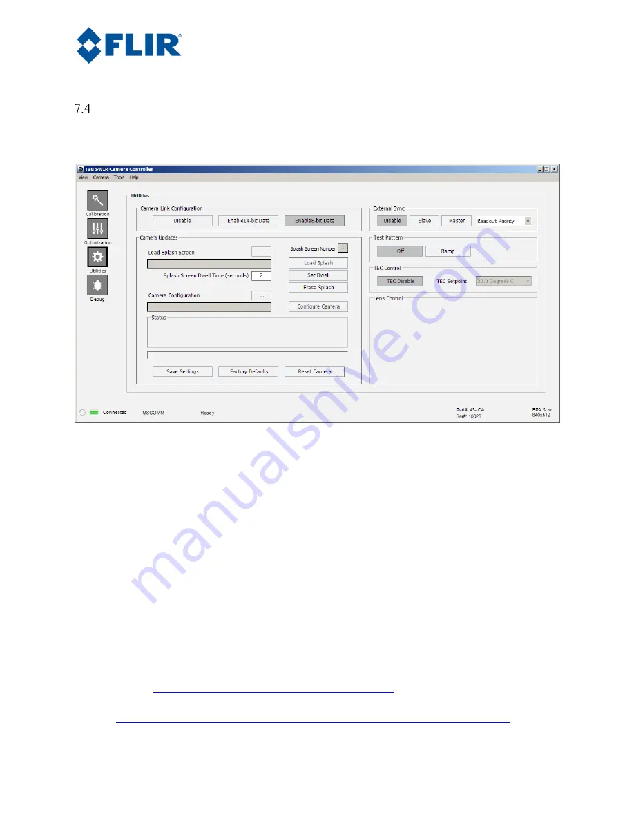
Utilities Tab
The Utilities tab on the FLIR Camera Controller GUI, shown below, provides the ability to configure the
camera’s analog output.
Figure 27. FLIR Camera Controller GUI -- Video Tab
Camera Link Configuration:
This section describes digital data acquisition with the Camera Link
accessory and assumes that all prior sections have been successfully completed.
1.
Connect one end of the Camera Link cable to the camera. The camera connection is a Mini-
Camera Link connector and frame grabbers may use either standard or Mini-Camera Link. It is
possible to purchase cables that have mini connectors on both ends or standard on one end with
mini on the other.
2.
Select either 14-bit or 8-bit data, depending upon preference. 8-bit data has the AGC applied and
looks similar to the analog video image. 14-bit data does not have AGC applied. Once these
changes are made, it is a good idea to save settings to make them power cycle persistent. This can
be done on the Setup Tab by clicking the “Save Settings” button.
3.
The digital data complies with Base Camera Link standards and will be compatible with most off-
the-shelf Camera Link frame grabbers. FLIR has tested the ImperX FrameLink Express frame
grabber (
http://imperx.com/frame-grabbers/framelink-express
) and the Matrox Solios Camera
Link frame grabber.
(
http://www.matrox.com/imaging/en/products/frame_grabbers/solios/solios_ecl_xcl_b/
). It is


