


Installation
9
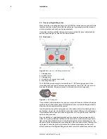
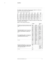
Pelco Address: This is the address of the system when configured as a Pelco device.
The available range of values is from decimal 0 to 255.
Table 9.1
Dip switch address/ID settings—SW102
ID
Bit 1
Bit 2
Bit 3
Bit 4
Bit 5
Bit 6
Bit 7
Bit 8
0
OFF
OFF
OFF
OFF
OFF
OFF
OFF
OFF
1
ON
OFF
OFF
OFF
OFF
OFF
OFF
OFF
2
OFF
ON
OFF
OFF
OFF
OFF
OFF
OFF
3
ON
ON
OFF
OFF
OFF
OFF
OFF
OFF
...
...
...
...
...
...
...
...
...
255
ON
ON
ON
ON
ON
ON
ON
ON
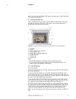
Other serial communication parameters: The tables below defines the switch locations,
bit numbering, and on/off settings.
Table 9.2
Dip switch address/ID settings—SW103
Settings
Descrip-
tion
Baud rate
: This is the baud rate of the system user serial
port. The available values are 2400, 4800, 9600, 19200
kbaud.
Bit 1
Bit 2
OFF
OFF
2400
ON
OFF
4800
OFF
ON
9600
ON
ON
19200
Camera control protocol
: This is the communication
protocol selected for the system when operating over the
serial port. The available protocols are Pelco-D and
Bosch.
Bit 3
Bit 4
OFF
OFF
Pelco-D
ON
OFF
N/A
OFF
ON
Bosch
ON
ON
N/A
Serial communication protocol
: This determines the
electrical interface selected for the user serial port. The
available settings are RS-422 and RS-232.
Bit 5
Bit 6
OFF
OFF
N/A
ON
OFF
RS-422
OFF
ON
RS-232
ON
ON
N/A
Not used.
Bit 7
Bit 8
X
X
X
X
X
X
X
X
Software override DIP switch
: This setting determines
whether the system will use software settings for configu-
ration or if the dip switch settings will override the soft-
ware settings. The default is Off.
Bit 9
OFF
Software
select
ON
Hardware
select
Not used.
Bit 10
X
#T559900; r. AB/35735/35735; en-US
16
Summary of Contents for G300 pt Series
Page 1: ...User s manual FLIR G300 pt ...
Page 2: ......
Page 3: ...User s manual FLIR G300 pt T559900 r AB 35735 35735 en US iii ...
Page 4: ......
Page 42: ...Mechanical drawings 13 T559900 r AB 35735 35735 en US 36 ...
Page 44: ...CE Declaration of conformity 14 T559900 r AB 35735 35735 en US 38 ...
Page 45: ......
Page 79: ......