


Installation
9
9.5
Prior to cutting/drilling holes
When selecting a mounting location for the FLIR G300 pt series camera, consider cable
lengths and cable routing. Ensure that the cables are long enough given the proposed
mounting locations and cable routing requirements.
Use cables that have sufficient dimensions to ensure safety (for power cables) and ad-
equate signal strength (for video and communications).
9.6
Back cover
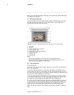
Figure 9.4
Back cover of a FLIR G300 pt series camera.
1. Shipping plug.
2. Breather valve.
3. Shipping plug.
4. Ground lug, for connection to earth.
5. Mounting screw (×6).
The FLIR G300 pt series camera comes with two ¾″ NPT cable glands, each with a
three-hole gland seal insert. Cables can be between 0.23″ and 0.29″ OD. Up to six ca-
bles may be installed. Plugs are required for the insert hole(s) not being used.
Figure 9.5
¾″ NPT cable gland.
If non-standard cable diameters are used, you may need to locate or fabricate the appro-
priate insert to fit the desired cable. FLIR Systems does not provide cable gland inserts
other than what is supplied with the system.
Insert the cables through the cable glands on the enclosure before terminating and con-
necting them. (In general, the terminated connectors will not fit through the cable gland.)
If a terminated cable is required, make a single clean cut in the gland seal to install the
cable into the gland seal.
Proper installation of cable sealing glands and use of appropriate elastomer inserts is
critical to long-term reliability. Cables enter the camera mount enclosure through liquid-
tight compression glands. Be sure to insert the cables through the cable glands on the
enclosure before terminating and connecting them (the connectors will not fit through the
cable gland). Leave the gland nuts loosened until all cable installation has been com-
pleted. Inspect and install gland fittings in the back cover with suitable leak sealant, and
#T559900; r. AB/35735/35735; en-US
13
Summary of Contents for G300 pt Series
Page 1: ...User s manual FLIR G300 pt ...
Page 2: ......
Page 3: ...User s manual FLIR G300 pt T559900 r AB 35735 35735 en US iii ...
Page 4: ......
Page 42: ...Mechanical drawings 13 T559900 r AB 35735 35735 en US 36 ...
Page 44: ...CE Declaration of conformity 14 T559900 r AB 35735 35735 en US 38 ...
Page 45: ......
Page 79: ......