


Installation
9
9.9
Video connections
The analog video connections on the back of the camera are BNC connectors.
The video cable used should be rated as RG59U or better to ensure a quality video
signal.
9.10
Ethernet connection
The cable gland seal is designed for use with shielded Category 6 Ethernet cable.
9.11
Serial communications overview
The installer must first decide if the serial communications settings will be configured via
hardware (DIP switch settings) or software. If the camera has an Ethernet connection,
then generally it will be easier (and more convenient in the long run) to make configura-
tion settings via software. Then, configuration changes can be made over the network
without physically accessing the camera. Also, the settings can be saved to a file, and
backed up or restored as needed.
If the camera is configured via hardware, then configuration changes in the future may
require accessing the camera on a tower or pole, dismounting it, removing the back, and
so on. If the camera does not have an Ethernet connection, the DIP switches must be
used to set the serial communication options.
Note
• The serial communications parameters for the FLIR G300 pt series camera are set or
modified either via hardware DIP switch settings or via software, through a web
browser interface. A single DIP switch (SW102-9, software override) determines
whether the configuration comes from the hardware DIP switches or the software
settings.
• The DIP switches are only used to control serial communications parameters. Other
settings, related to IP camera functions and so on, must be modified via software (us-
ing a web browser).
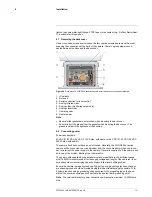
9.12
Serial connections
For serial communications, it is necessary to set the parameters such as the signalling
standard (RS-232 or RS-422), baud rate, number of stop bits, parity, and so on. It is also
necessary to select the communication protocol used (either Pelco D or Bosch) and the
camera address.
The camera supports RS-422 and RS-232 serial communications using common proto-
cols (Pelco D, Bosch).
Note
The terminal blocks for serial connections will accept a maximum 20 AWG wire
size.
9.13
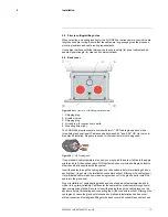
Setting configuration dip switches
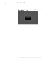
The figure below shows the locations of dip switches SW102 and SW103.
Figure 9.7
Dip switch locations in the FLIR G300 pt series camera.
#T559900; r. AB/35735/35735; en-US
15
Summary of Contents for G300 pt Series
Page 1: ...User s manual FLIR G300 pt ...
Page 2: ......
Page 3: ...User s manual FLIR G300 pt T559900 r AB 35735 35735 en US iii ...
Page 4: ......
Page 42: ...Mechanical drawings 13 T559900 r AB 35735 35735 en US 36 ...
Page 44: ...CE Declaration of conformity 14 T559900 r AB 35735 35735 en US 38 ...
Page 45: ......
Page 79: ......