


Installation
9
tighten to ensure water-tight fittings. PTFE tape or pipe sealant (e.g., DuPont RectorSeal
T) is suitable for this purpose.
9.7
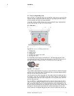
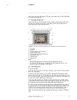
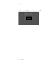
Removing the back cover
Use a cross-head screwdriver to loosen the four captive screws and remove the cover,
exposing the connections at the back of the camera. There is a grounding wire con-
nected between the case and the back cover.
Figure 9.6
Rear view of a FLIR G300 pt series camera, after the back cover has been released.
1. IP network.
2. Not used.
3. Serial connection for local control.
4. Analog infrared video.
5. Analog video (monitoring output only).
6. Analog visual video.
7. Camera power.
8. Heater power.
Note
• Be careful that gaskets are not pinched when mounting the back cover.
• Do not wipe off the grease from the gaskets when mounting the back cover. The
grease is critical to the tightness of the housing.
9.8
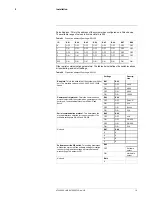
Connecting power
Power requirements:
24 VAC (21-30 VAC; 24 VAC: 215 VA max. with heater) or 24 VDC (21-30 VDC; 24 VDC:
200 W max. with heater).
The camera itself does not have an on/off switch. Generally, the FLIR G300 pt series
camera will be connected to a circuit breaker, and the circuit breaker will be used to con-
nect or interrupt the power supply to the camera. If power is supplied to it, the camera will
be in one of two modes: Booting Up or Powered On.
The power cable supplied by the installer must use wires that are of a sufficient gauge
size (16 AWG is recommended) for the supply voltage and length of the cable run, to en-
sure adequate current-carrying capacity. Always follow local building codes.
Ensure the camera is properly grounded. Typical to good grounding practices, the cam-
era chassis ground should be provided using the lowest resistance path possible. FLIR
Systems requires using a grounding strap anchored to the grounding lug on the back
plate of the camera housing and connected to the nearest earth-grounding point.
Note
The terminal blocks for power connections will accept a maximum 16 AWG wire
size.
#T559900; r. AB/35735/35735; en-US
14
Summary of Contents for G300 pt Series
Page 1: ...User s manual FLIR G300 pt ...
Page 2: ......
Page 3: ...User s manual FLIR G300 pt T559900 r AB 35735 35735 en US iii ...
Page 4: ......
Page 42: ...Mechanical drawings 13 T559900 r AB 35735 35735 en US 36 ...
Page 44: ...CE Declaration of conformity 14 T559900 r AB 35735 35735 en US 38 ...
Page 45: ......
Page 79: ......