


S E T U P F O R M
C H A P T E R 4
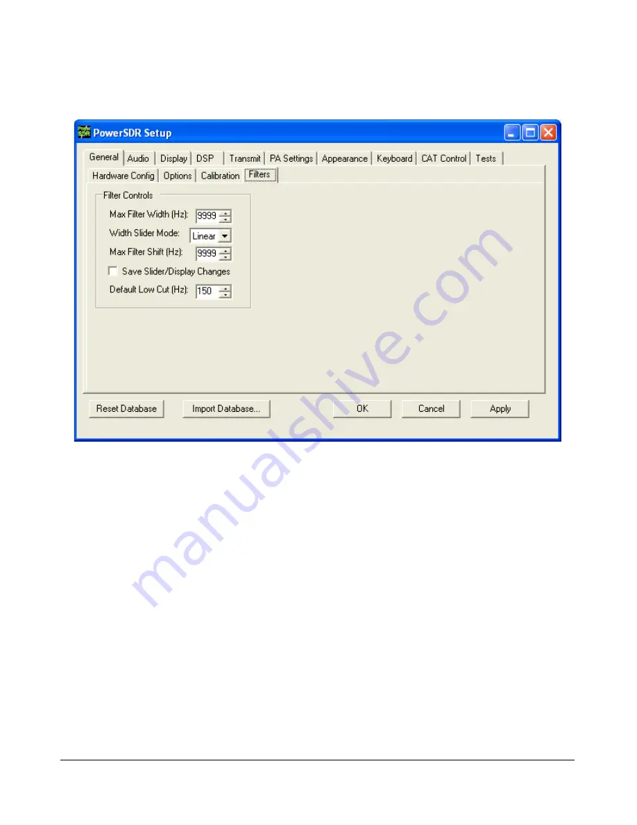
Filters Sub-Tab
Figure 69: Setup Form - General Tab, Filters Sub-Tab
Max Filter Width
: Sets the maximum filter width to be set by the Filter Width Slider on the
front console.
Width Slider Mode
: Sets the behavior of the Width Slider. Linear, Log, and Log10 are the
options. The log options offer more resolution on the smaller filter sizes.
Max Filter Shift
: Sets the maximum swing in Hz that the Filter Shift Slider on the front panel
will allow in either direction.
Save Slider/Display Changes
: If checked, any changes to the filters made by the filter
sliders or by using the click and drag on the filter edges on the display will be saved to the
Variable filters and will be recalled as such. If not checked, the Var filters can only be changed
by adjusting the Filter Low and High Cut controls on the front panel.
Default Low Cut (Hz)
: Sets the default low frequency cut-off for the USB/LSB filters.
[The rest of this page has been left blank intentionally]
70
2003-2009 FlexRadio Systems


