


1
IMPO
RTAN
T:
Go to www
.extron.com
for the
complete user guide
, installation
instructions,
and specifications.
XTP SFR HD 4K • Setup Guide
CLASS 1 LASER PRODUCT,
see
the
XTP SFR HD 4K
User Guide
The Extron XTP SFR HD 4K is an XTP fiber receiver that scales HDMI, DVI, RGB, HD component video, and standard definition
video to the optimal output resolution. This guide provides instructions for an experienced installer to install and connect the
XTP SFR HD 4K scaling receiver.
Installation
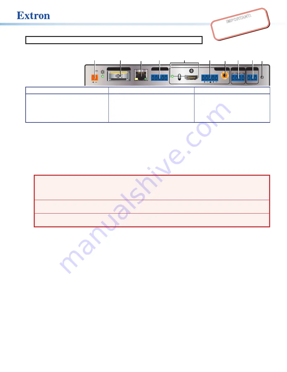
Rear Panel Features
Power and Throughput Connections
Output Connections
Control Connections and Reset
A
DC power connector and power LED
B
XTP input connector
C
LAN connector and LEDs
D
RS-232 and IR Over XTP connector
E
HDMI output connector and
corresponding HDMI audio switch
F
Analog audio output connector
G
S/PDIF digital audio output connector
H
Relay connectors
I
Remote RS-232 connector
J
Reset button
Figure 1.
Rear Panel Features
Mounting and Cabling
Step 1 — Mount the device
Turn off or disconnect all equipment power sources and mount the XTP SFR HD 4K on a tabletop or in a rack.
Step 2 — Connect throughput devices
a.
Connect an XTP transmitter or XTP matrix switcher to the XTP fiber input connector (
B
).
WARNING:
Potential risk of severe injury.
The XTP SFR HD 4K outputs continuous invisible light (class 1 laser rated),
which may be harmful to the eyes; use with caution.
AVERTISSEMENT :
Risque potentiel de blessure grave ou de mort.
Le XTP SFR HD 4K émet une lumière invisible
en continu (conforme à la classe 1 laser) qui peut être dangereux pour les yeux, àutiliser avec précaution.
•
Do not look into the fiber optic cable connector or into the fiber optic cables themselves.
•
Ne regardez pas dans le connecteur de câble fibre optique sur le ou dans les câbles fibre optique euxmêmes.
•
Plug the attached dust caps into the connector when the fiber optic cable is unplugged.
•
Branchez la protection contre la poussière dans le connecteur lorsque le câble fibre optique est débranché.
Signal LED indicator
— Lights green when it receives an active XTP input signal from a transmitter or matrix switcher.
Link LED indicator
— Lights yellow when a valid link between an XTP input and output is established.
b.
Connect a host device or control LAN or WAN to the LAN RJ-45 connector (
C
) for pass-through 10/100 Ethernet
communication. These are Ethernet pass-through ports with LEDs to indicate link and activity status.
c.
To pass bidirectional serial, infrared, or other control signals, connect a control device or a device to be controlled to the
RS-232 and IR Over XTP connector (
D
). See
Step 3 — Connect outputs
a.
Connect a digital video display to the HDMI output connector (
E
) on the receiver.
b.
Connect a balanced or unbalanced stereo or mono audio device to the 3.5 mm, 5-pole captive screw connector (
F
) on the
receiver for 2-channel stereo analog audio (see
on page 2 for wiring details).
c.
Connect an audio device to the female orange RCA connector (
G
) tor for digital S/PDIF audio output.
Step 4 — Connect control devices
a.
Connect a host device, such as a computer, to the front panel female USB mini-B connector (see
,
B
on page 2) to
configure the device or update firmware.
b.
Connect equipment controlled via momentary or latching contact, like projector screens or lifts, to these normally open
relays (
H
). Do not exceed 24 V at 1 A for each port.
c.
For serial control of the scaler, connect a host device to the Remote RS-232 3.5 mm, 3-pole captive screw connector (
I
).
Step 5 — Connect power
Connect the provided external power supply to the 2-pole captive screw connector (
A
).
POWER
12V
1.0 A MAX
HDMI
S/PDIF
AUDIO
AUDIO
SIG
LINK
LAN
RS-232
RS-232
IR
L
Tx Rx
Tx Rx
RESET
G
R
1
2
ON
OFF
XTP IN
OVER XTP
OUTPUTS
RELAYS
Tx Rx G
REMOTE
A
B
C
D
E
F
G
H
I J


