background image

6  Mounting
6.2  Transducers

FLUXUS G801

2020-06-26, UMFLUXUS_G801V1-0EN

56

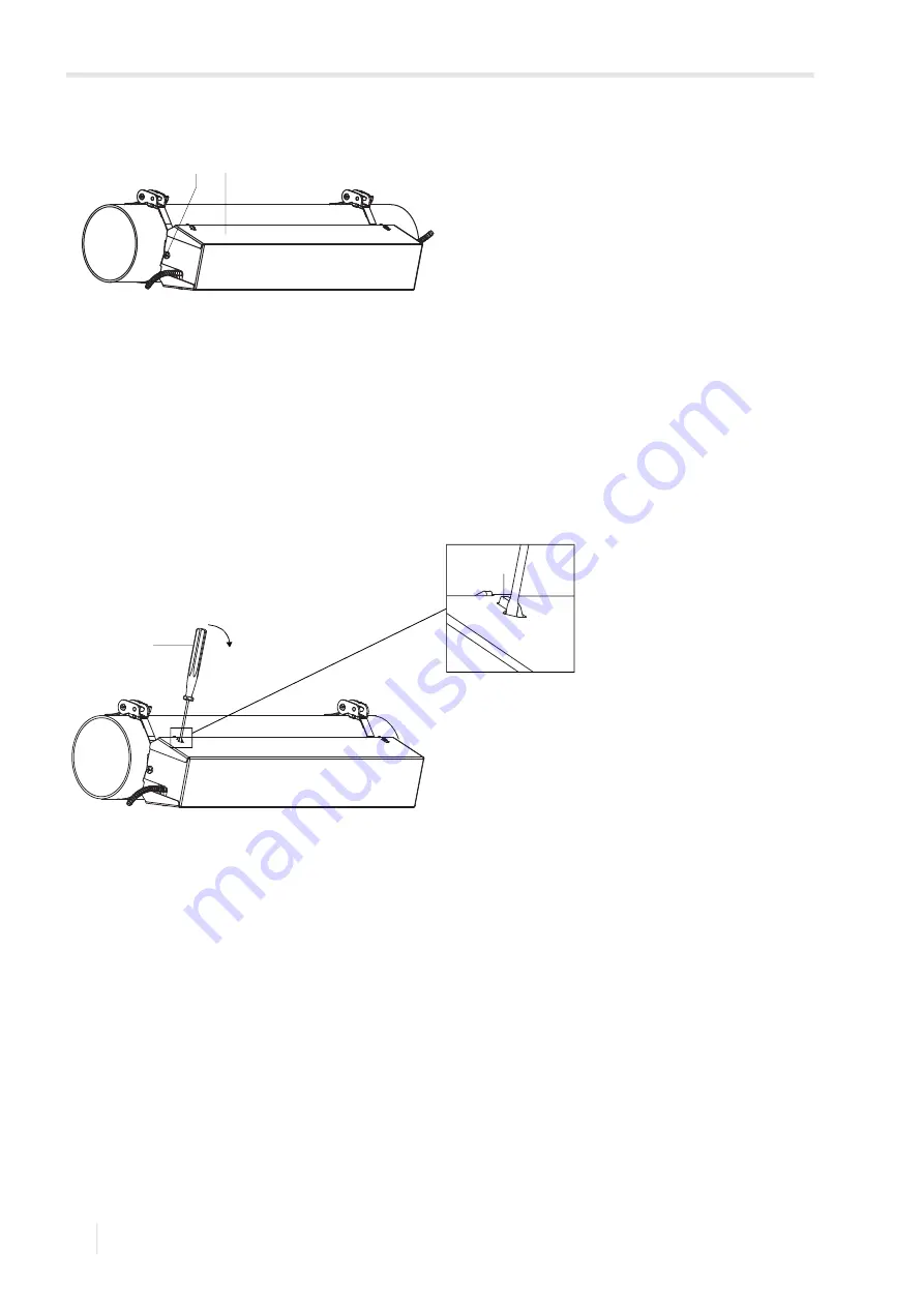
Remove the cover from the mounted transducer mounting fixture Variofix C as follows:
• Use a lever tool to remove the cover.
• Insert the lever tool in one of the 4 openings of the cover (see Fig. 6.51).
• Press the lever tool against the fixture.
• Bend the cover outwards and release it from the anchoring.
• Repeat the steps for the other 3 openings.
• Remove the cover from the rail.

Fig. 6.50: Variofix C with transducers on the pipe

1 – screw

2 – cover

Fig. 6.51: Removal of the cover

1 – lever tool

2 – fixture

1

2

2

1

Summary of Contents for FLUXUS G801

Page 1: ...FLUXUS G801 UMFLUXUS_G801V1 0EN Operating instruction...

Page 2: ...660 Fax 49 30 936 67 680 E mail info flexim com www flexim com FLUXUS is a registered trademark of FLEXIM GmbH Operating instruction for FLUXUS G801 UMFLUXUS_G801V1 0EN 2020 06 26 Article number 2164...

Page 3: ...penetration 16 3 4 Undisturbed flow profile 16 3 5 Influence of noise 18 3 6 Selection of the measuring point taking into account the flow profile and the influence of noise 19 4 Product description 2...

Page 4: ...ibration 109 11 4 Examination of the O ring 110 11 5 Examination of the thread on the flameproof enclosure housing 111 11 6 Examination of housing and sight glass 111 12 Dismounting and disposal 112 1...

Page 5: ...mode 145 17 1 Activation deactivation 145 17 2 Transducer parameters 146 17 3 Definition of the flow parameters 146 17 4 Limit of the signal amplification 148 17 5 Upper limit of the sound speed 149...

Page 6: ...Table of contents FLUXUS G801 2020 06 26 UMFLUXUS_G801V1 0EN 6...

Page 7: ...ion or miss information please inform us We will be grateful for any suggestions and comments regarding the concept and your experience working with the measuring equipment If you have any suggestions...

Page 8: ...tions for the disposal of electrical equipment 2 2 Intended use The measuring equipment is intended for the measurement of fluid properties in closed pipes By means of connected transducers the transi...

Page 9: ...s and spare parts may only be replaced by FLEXIM The operator shall carry out periodic checks for changes or damages that can present a danger For further information contact FLEXIM Observe the specif...

Page 10: ...transmitter transducers and accessories in the middle of the cardboard box Fill any voids with appropriate packaging material e g paper foam bubble wrap Protect the cardboard box against humidity 2 8...

Page 11: ...technical applications the flow in the pipe is mostly turbulent Transition range The flow is partly laminar and partly turbulent Sound speed c Speed of the propagating sound The sound speed depends o...

Page 12: ...f the flow velocity The signals are emitted and received by two transducers alternatively in and against the flow direction If the fluid is flowing the signals propagating in the fluid are displaced w...

Page 13: ...e signal against the flow direction c sound speed 1 transducer emitter 2 transducer receiver 3 pipe wall Fig 3 3 Transit time difference t 1 signal in the flow direction 2 signal against the flow dire...

Page 14: ...e the transducer emitting the ultrasonic signal and the transducer receiving it One beam consists of 1 or several sound paths Transducer distance The transducer distance is measured between the inner...

Page 15: ...3 7 2 sound paths in 1 plane diagonal arrangement with 1 beam reflection arrangement with 1 beam 1 transducer pair 1 sound path 1 beam 1 plane 1 transducer pair 2 sound paths 1 beam 1 plane diagonal a...

Page 16: ...bottom of the pipe or gas bubbles in the pipe s upper part are prevented from influencing the propagation of the signal 3 4 Undisturbed flow profile Some flow elements e g elbows valves pumps reducers...

Page 17: ...lanes inlet l 40 D outlet l 5 D disturbance valve inlet l 40 D outlet l 5 D disturbance reducer inlet l 10 D outlet l 5 D disturbance compressor inlet l 20 D Tab 3 1 Recommended distance from disturba...

Page 18: ...e time Measuring points to be avoided measuring point directly at the reflection point l 3 D measuring point at a distance of lS 2 D from the reflection point pipe wall signal and measuring signal are...

Page 19: ...profile as possible Example fluid natural gas c 400 m s pipe material stainless steel c 3000 m s length of pipe segment 1 20 D length of pipe segment 2 20 D number of sound paths 2 ls 7 5 D area with...

Page 20: ...te pipe segment 2 area with low influence of noise reflection point flange recommended area for the measuring point l 3 D and outside of lS 7 5 2 D on pipe segment 1 Fig 3 13 Area for the measuring po...

Page 21: ...als The measured values can be displayed used for calculations and transmitted 4 2 Handling concept The command panel is on the front side of the housing The keys are operated by a magnetic pen with c...

Page 22: ...scroll and select a list item in the upper line Press to scroll and select a value for the selected list item in the lower line Press ENTER 4 3 2 Input fields Press and to enter the value Press ENTER...

Page 23: ...urement by inadvertently pressing BRK Tab 4 3 Navigation scroll to the right or up through a scroll list scroll to the left or down through a scroll list Tab 4 4 Input of numbers move the cursor to th...

Page 24: ...cardboard box against humidity 5 2 Storage Store the measuring equipment in a dry place Caution When packaging the transmitter can fall down There is a danger of crushing body parts or damaging the me...

Page 25: ...qualified personnel Danger Working in mines or cramped confines Risk of intoxication and or asphyxiation because of emerging gases risk of injuries because of cramped conditions Wear the required pers...

Page 26: ...sing can be opened Use 2 strap wrenches not included in the delivery to open and close the housing After the installation make sure that the housing is closed correctly and that the countersunk screw...

Page 27: ...rews 3 6 1 2 2 Pipe mounting Installation on a 2 pipe Position the shackles 1 on the pipe Fix the instrument mounting plate 2 to the pipe using the shackles 1 and nuts 4 Fix the transmitter to the ins...

Page 28: ...e pipe fluid Avoid measuring points in the vicinity of distorted or defective areas of the pipe or in the vicinity of welds Avoid measuring points with deposit formation in the pipe Make sure the pipe...

Page 29: ...measurement arrangement Caution Contact with grinding dust This may result in injuries e g breathing difficulties skin reactions eye irritations Wear the required personal protective equipment Observe...

Page 30: ...flow profile are compensated because the measurement takes place in 2 planes same characteristics as diagonal arrangement with 1 beam additional characteristic transverse flow effects are compensated...

Page 31: ...ted lengthwise on the pipe The mounting depends on the outer pipe diameter 900 mm The transducer damping mats are mounted on the entire pipe circumference 900 mm The transducer damping mats are only p...

Page 32: ...ng The paint does not need to be removed completely Remove any rust or loose paint Remove any grease or dust Clean the pipe surface with soap suds Determine the number and size of the damping mats tha...

Page 33: ...chnical specification section Damping mats Repeat the steps for mounting the damping mats If possible make sure not to mount the transducers on the seams between the damping mats If the transducers ar...

Page 34: ...flection point 1 reflection point 2 reflection points 2 reflection points 1 transducer mounting fixture 2 transducer damping mats 3 pipe damping mats 4 reflection point lS1 mounting length of the tran...

Page 35: ...ounting length is 1010 mm Fig 6 7 Outer pipe diameter 900 mm 1 transducer damping mats 2 pipe damping mats 3 reflection point The transducer damping mats are mounted lengthwise on the pipe The pipe da...

Page 36: ...nt 1 reflection point 2 reflection points 2 reflection points 1 transducer mounting fixture 2 transducer damping mats 3 pipe damping mats 4 reflection point lS1 mounting length of the transducer dampi...

Page 37: ...mats are mounted lengthwise on the pipe The pipe damping mats can be mounted lengthwise or crosswise on the pipe In this example they are mounted crosswise Number of transducer damping mats The trans...

Page 38: ...rections The transducer distance is measured between the inner edges of the transducers Select the installation instructions that correspond to the supplied transducer mounting fixture 6 2 3 2 Transdu...

Page 39: ...cers LI is removed from the transducer cable during installation it has afterwards to be remounted and fixed to the transducer cable using the provided cable tie The heat shrink tubing must not be reu...

Page 40: ...06 26 UMFLUXUS_G801V1 0EN 40 6 2 3 4 Mounting with Variofix L PermaRail Scope of delivery 2 Variofix L 1 transducer pair 4 quick release clasp with tension strap or 4 band clamp clasp with tension str...

Page 41: ...lection arrangement is described 1 transducer mounting fixture for each transducer Overview of the mounting steps step 1 disassembly of the transducer mounting fixture Variofix L step 2 fixation of th...

Page 42: ...instruction of the supplied clasp Band clamp clasp The clasp is fixed to the tension strap see Fig 6 15 Quick release clasp The clasp is fixed to the tension strap see Fig 6 16 Cut the tension strap...

Page 43: ...r Select the installation instruction of the supplied clasp Band clamp clasp Insert the tension strap into its clamp see Fig 6 19 Position the clasp and the tension strap clamp on the pipe see Fig 6 1...

Page 44: ...ter 80 mm pipes that are not subjected to significant temperature fluctuations Position the ratchet clasp tension strap clamp and metal spring if necessary on the pipe see Fig 6 18 On a horizontal pip...

Page 45: ...on strap clamp 1 see Fig 6 25 Tighten the nut of tension strap clamp 1 but not too firmly in order not to damage the tension strap Notice In order to release the screw and the tension strap press the...

Page 46: ...trap see Fig 6 26 Quick release clasp Insert the tension strap into its clamp 2 and the metal spring see Fig 6 26 and Fig 6 28 Place the tension strap around the pipe and insert it into the clasp Posi...

Page 47: ...of the clasp screw see Fig 6 30 Tighten the tension strap Cut off the protruding tension strap see Fig 6 30 Tighten the clasp screw Tighten the nut of the tension strap clamp 2 but not too firmly in o...

Page 48: ...f clamp to protect them from mechanical strain see Fig 6 33 Put coupling foil or apply some coupling compound for a short term installation on the contact surface of the transducers The coupling foil...

Page 49: ...cover 2 strain relief clamp 3 equipotential bonding terminal a transducer distance Notice Make sure that the coupling foil remains on the contact surface of the transducers For information concerning...

Page 50: ...es of the pipe In the following the installation of 1 transducer mounting fixture in reflection arrangement is described Overview of the mounting steps step 1 disassembly of the transducer mounting fi...

Page 51: ...lift it off Step 2 Mounting the rail Select the installation instruction of the supplied clasp Mounting of the rail without a clasp Cut the tension strap to length pipe circumference at least 120 mm F...

Page 52: ...laterally to the pipe if possible mount the metal spring if necessary opposite to the tension strap clamp Insert the long end of the tension strap into the second slot of the tension strap clamp see F...

Page 53: ...nsion strap into its clamp and the metal spring see Fig 6 44 The metal spring does not have to be mounted on steel pipes pipes with an outer diameter 80 mm pipes that are not subjected to significant...

Page 54: ...t off the protruding tension strap see Fig 6 46 Tighten the screw of the ratchet clasp Repeat the steps for the second tension strap Put the rail on the tension strap clamps see Fig 6 47 Fix the rail...

Page 55: ...tly The end of the tensioning screw has to be placed above the hole in the transducer see Fig 6 48 and Fig 6 49 Correct the transducer distance if necessary Tighten the tensioning screws Fix the spaci...

Page 56: ...e the cover Insert the lever tool in one of the 4 openings of the cover see Fig 6 51 Press the lever tool against the fixture Bend the cover outwards and release it from the anchoring Repeat the steps...

Page 57: ...personal or material damage or dangerous situations Any work on the transmitter has to be carried out by authorized and qualified personnel Danger Working in mines or cramped confines Risk of intoxic...

Page 58: ...enings is closed with a blind plug It is recommended to run the cables from the measuring point to the transmitter before connecting the transducers to avoid load on the connectors Fig 7 1 Connections...

Page 59: ...ble into the housing Fix the cable gland by screwing the cap nut onto the basic part Connect the transducer cable to the terminals of the transmitter Fig 7 3 Connection of the transducers to the trans...

Page 60: ...tion of the transducer cable with plastic jacket and stripped ends to the transmitter FLUXUS 801 A10 AA 801 A10 AP FLUXUS 801C24 801 A10 FF 1 cap nut 2 compression part 3 basic part 4 external shield...

Page 61: ...the transducer cable by tightening the cable gland Connect the transducer cable to the terminals of the transmitter Tab 7 2 Terminal assignment terminal connection AV transducer brown cable marked wh...

Page 62: ...e basic part into the transmitter housing Insert the extension cable into the housing Fix the cable gland by screwing the cap nut onto the basic part Connect the extension cable to the terminals of th...

Page 63: ...de of the basic part into the junction box Insert the transducer cable into the junction box Fix the cable gland by screwing the cap nut onto the basic part Connect the transducer cable to the termina...

Page 64: ...e transducer cables by tightening the cable glands Connect the transducer cable to the terminals of the junction box Fig 7 7 Connection of the transducer cable with plastic jacket and stripped ends 1...

Page 65: ...extension cable Open the cable gland of the extension cable The compression part remains in the cap nut Push the extension cable through the cap nut and the compression part Prepare the extension cabl...

Page 66: ...cable internal shield TRS brown cable internal shield TR brown cable core cable gland external shield Fig 7 9 Connection of the extension and transducer cable to the junction box 1 extension cable 2...

Page 67: ...Insert the extension cable into the junction box Prepare the extension cable Cut the external shield and brush it back Pull the extension cable back until the brushed back external shield is below the...

Page 68: ...Connection of the extension and transducer cable to the junction box 1 extension cable 2 external shield 3 shield terminal 4 cap nut 5 compression part 6 basic part 7 connection of the extension cable...

Page 69: ...replaced or added the transducer module has to be replaced or added as well Notice The serial numbers of the transducer module and the transducer have to be identical A wrong or incorrectly connected...

Page 70: ...mitter The external protective earth is connected to the equipotential bonding terminal on the transmitter housing Connect the power cable to the transmitter see section 7 2 1 Fig 7 12 and Tab Tab 7 8...

Page 71: ...o the housing of the transmitter Screw the sealing ring side of the basic part into the transmitter housing Fix the cable gland by screwing the cap nut onto the basic part Connect the cable to the ter...

Page 72: ...ansmitter fault Ifault 0 mA HART interface activated or as current output 801 A10 A 801 A10 P active Uint 24 V current during transmitter fault Ifault 0 mA passive Uext 10 24 V current during transmit...

Page 73: ...ext 5 24 V Rc k Uext Ic mA Ic 1 4 mA binary output Reed relay 801 A10 A 801 A10 P Umax 48 V Imax 100 mA RS485 801 A10 A 801 A10 P 120 termination resistor Tab 7 9 Output circuits output transmitter ex...

Page 74: ...of the alarm output If the transmitter is disconnected from the power supply the binary output indicates an alarm state Fig 7 15 Connection of the outputs to the transmitter FLUXUS 801C24 1 partition...

Page 75: ...to the RS232 adapter Connect the RS232 cable to the transmitter and the serial interface of the PC If the RS232 cable cannot be connected to the PC use the RS232 USB adapter The RS232 USB adapter and...

Page 76: ...hyxiation because of emerging gases risk of injuries because of cramped conditions Wear the required personal protective equipment Observe the applicable rules Warning Touching live parts Electric sho...

Page 77: ...ial Press ENTER Select yes if the transmitter is to be used in the region of Canada Press ENTER This display will only be indicated if imperial is selected The current time is displayed Press ENTER to...

Page 78: ...EM settings contains the following menu items dialogs and menus measurement outputs storing snap network serial transmission miscellaneous clock settings libraries Tab 8 1 Operation state of the trans...

Page 79: ...isplayed in the selected language The selected language remains activated when the transmitter is switched off and on again After an initialization of the transmitter the language is reset to default...

Page 80: ...at the current settings Press ENTER If yes is selected the message FACTORY DEFAULT DONE will be displayed Select yes to delete the stored measured values or no to keep them Press ENTER This display w...

Page 81: ...ed in the lower line Press ENTER 8 9 Interruption of the power supply As soon as the measurement begins all current measuring parameters will be stored in a non volatile INIT resistant EPROM In case o...

Page 82: ...n personal or material damage or dangerous situations Any work on the transmitter has to be carried out by authorized and qualified personnel Danger Working in mines or cramped confines Risk of intoxi...

Page 83: ...t is possible to enter the pipe circumference instead of the outer pipe diameter If the input of the pipe circumference is activated and zero is entered in Outer Diameter the menu item Pipe Circumfer...

Page 84: ...lining Press ENTER Lining material Select the lining material If the lining material is not included in the scroll list select Other Material Press ENTER This display will only be indicated if yes is...

Page 85: ...e disturbance distance Enter the disturbance distance Press ENTER This display will only be indicated if With disturbance is selected in the menu item Special Funct SYSTEM settings Measuring ProfileCo...

Page 86: ...dium is selected Gas compressibility coefficient The compressibility coefficient of the gas is essential for the calculation of the standard volumetric flow rate Make sure that the value is selected a...

Page 87: ...d the transducer parameters have to be entered Select Standard to use the standard transducer parameters stored in the transmitter Select Special Version to enter the transducer parameters The transdu...

Page 88: ...physical quantity For the selected physical quantity except for the sound speed a scroll list with the available units of measurement is displayed The unit of measurement which was selected previously...

Page 89: ...transmitter is equipped with outputs they have to be installed and activated before they can be used assignment of a measuring channel source channel to an output if the transmitter has more than one...

Page 90: ...ist select the measuring channel to be assigned to the output as the source channel Press ENTER This display will not be indicated if the transmitter has only one measuring channel Assignment of a sou...

Page 91: ...zer for the physical quantity selected in the program branch Output Options Flow flow totalizer Q sum of the totalizers positive and negative flow direction actual measure totalizer for the physical q...

Page 92: ...lected enter an error value The value has to be within the output range Press ENTER Source item Output range Error value active loop Output Test see annex A Special Funct SYSTEM settings Proc outputs...

Page 93: ...t will be displayed whether the current output is active or passive here active Tab 9 3 Examples for the error output output range 4 20 mA list item output signal Minimum 4 0 mA Hold last value Maximu...

Page 94: ...ing channel Press ENTER until Current Loop is displayed Select yes to activate the output Press ENTER Measuring range After an analog output has been activated in the program branch Output Options the...

Page 95: ...elect yes to test the output Press ENTER Enter a test value for the selected physical quantity If the measuring instrument displays the entered value the output functions correctly Press ENTER Select...

Page 96: ...transmitter has only one measuring channel Select a channel with Press to activate or deactivate the channel Press ENTER A deactivated channel will be ignored during the measurement The parameters ent...

Page 97: ...one transducer pair at the measuring point inappropriate measurement arrangement The profile correction 2 0 at non ideal inflow conditions cannot be used The profile correction 2 0 at ideal inflow con...

Page 98: ...Parameter or the exact parameters of the fluid are unknown a consistency check is recommended The transducer distance can be displayed during the measurement by scrolling with The optimum transducer...

Page 99: ...rement by pressing If an approximate range for the sound speed has been entered in the program branch Parameter and the transducer distance has been optimized afterwards it is recommended to write dow...

Page 100: ...ronized The channel on which a measurement is being made is displayed in the upper line on the left Measuring channels only The measured values of all measuring channels are displayed The next activat...

Page 101: ...ity and precision of the running measurement can be evaluated accordingly Press during the measurement to scroll through the upper line to the status line display explanation 12 3 m s flow velocity 14...

Page 102: ...file information about the flow profile based on the Reynolds number T fully turbulent flow profile L fully laminar flow profile transition range between laminar and turbulent flow unknown cannot be c...

Page 103: ...ive e g 54 5 m h 9 7 Stop of the measurement The measurement is interrupted by pressing BRK if it is not protected by a program code Tab 9 6 Commands that can be executed during the measurement comman...

Page 104: ...lified personnel Danger Working in mines or cramped confines Risk of intoxication and or asphyxiation because of emerging gases risk of injuries because of cramped conditions Wear the required persona...

Page 105: ...outputs are configured correctly Check the function of the output If the output is defective contact FLEXIM 10 1 Problems with the measurement A measurement is not possible because no signal is recei...

Page 106: ...to measure on a section of the pipe free from lining Droplets or solid particles present in high concentration in the fluid scatter and absorb the ultrasonic signal and thus attenuate the measuring s...

Page 107: ...he totalizers will be stored The totalizers will continue with these values when starting the next measurement The values of the totalizers are too small One of the totalizers has reached the upper li...

Page 108: ...d and qualified personnel Danger Working in mines or cramped confines Risk of intoxication and or asphyxiation because of emerging gases risk of injuries because of cramped conditions Wear the require...

Page 109: ...show visible wear the transducers were used for a prolonged period at high temperatures several months 130 C for normal transducers or 200 C for high temperature transducers In order to realize a reca...

Page 110: ...hermetically sealed and dark place Housing with increased safety Defective O rings have to be replaced Danger Risk of explosion when using the transmitter in explosive atmospheres This may result in p...

Page 111: ...ularly checked for damages Cracked or scratched sight glasses or damaged housings have to be replaced by FLEXIM personnel immediately Danger Risk of explosion when using the transmitter in explosive a...

Page 112: ...s may result in personal or material damage or dangerous situations Any work on the transmitter has to be carried out by authorized and qualified personnel Danger Working in mines or cramped confines...

Page 113: ...12 2 Disposal The measuring equipment has to be disposed of in accordance with the applicable regulations Important Avoiding environmental damage by correct disposal of components Depending on the mat...

Page 114: ...the program branch Output Options Select the menu item Proc outputs Press ENTER Selection of a binary output Select the binary output to be installed Press ENTER Select yes to install or reconfigure t...

Page 115: ...menu item SYSTEM settings Press ENTER Select Reed Relay ON or Open collect ON in the scroll list Output Test to test the energized state of the output Press ENTER Measure the resistance at the output...

Page 116: ...channel to be assigned to the frequency output as the source channel Press ENTER This display will not be indicated if the transmitter has only one measuring channel Select Measuring value but not Im...

Page 117: ...el Press ENTER until Frequency Output is displayed Select yes to activate the output Press ENTER Enter the number of pulses that is to be assigned to the unit of measurement of the totalizer Press ENT...

Page 118: ...this case because the integration of the flow velocity does not result in a reasonable value Enter the pulse value The unit of measurement will be displayed according to the actual physical quantity...

Page 119: ...ed in the program branch Output Options Press ENTER This display will not be indicated if the transmitter has only one measuring channel Press ENTER until Store Meas Data is displayed Select yes to ac...

Page 120: ...ed Select ON to activate the ringbuffer Press ENTER Storage mode Select the storage mode Press ENTER If sample is selected the current measured value will be used for the storing and online transmissi...

Page 121: ...agnostic values together with the measured values Press ENTER Option of flow velocity storing Enter the HotCode 007043 Select auto to store the flow velocity as an integer Select full to store the flo...

Page 122: ...ns Store Meas Data is activated and the menu item Special Funct SYSTEM settings Ringbuffer is deactivated a message will be displayed as soon as the data logger is full Press ENTER The message will be...

Page 123: ...red values before starting a measurement The type and the serial number of the transmitter are displayed in the upper line The remaining data logger capacity will be displayed in the lower line here 1...

Page 124: ...2 1 Online transmission The measured values are transmitted during the measurement The data logger works independently of the online transmission but with the same transmission rate Start the termina...

Page 125: ...RS485 Transmitter settings Select the menu item Print Meas Val Press ENTER The following message will be displayed if no measured values are stored Press ENTER The following message will be displayed...

Page 126: ...t the menu item Network to change the settings of the transmission parameters Press ENTER This display will only be indicated if the transmitter has an interface RS485 Press ENTER to confirm the devic...

Page 127: ...ansmitter and the measurement The following lines contain the parameters for each channel Next the line DATA is transmitted followed by the column titles for the corresponding channel The measured val...

Page 128: ...be generated Offline transmission During the offline transmission of data columns will only be created if at least one measured value is stored in the data set The columns Q_POS and Q_NEG will not be...

Page 129: ...R Automatic display toggling The automatic toggling of the totalizer display between positive and negative flow direction can be set Enter a time interval between 0 off and 5 s Press ENTER Totalizer s...

Page 130: ...rs The upper limit of the flow velocity is set in the menu item Special Funct SYSTEM settings Measuring Velocity limit Enter zero to switch off the outliers check Enter a limit 0 to switch on the outl...

Page 131: ...ction A limit is set for the absolute value of the flow velocity Press ENTER Select factory to use the default limit of 2 5 cm s 0 025 m s for the cut off flow Select user to enter the cut off flow Pr...

Page 132: ...asuring Press ENTER until the menu item ProfileCorr 2 0 is displayed Select a list item default on Press ENTER Input of the disturbance distance If With disturbance is selected in the menu item Specia...

Page 133: ...nging measuring conditions is only partially realized in the FastFood mode The sound speed of the fluid is not updated The last measured value of the sound speed before toggling to the FastFood mode i...

Page 134: ...the selected calculation channel This measured value is equivalent to the measured values of a measuring channel All functions which are possible with the measured values of a measuring channel totali...

Page 135: ...s selected The measured values of the calculation channel here Y will be valid if the measured values of both measuring channels here A and B are valid If only one measuring channel provides valid mea...

Page 136: ...t yes to activate the data logger or no to deactivate it Press ENTER Tab 16 1 physical quantity of the calculation channel possible physical quantity of the first measuring channel possible physical q...

Page 137: ...cted the measured values of the measuring channels will be displayed alternately but not the measured values of the calculation channels Press to display the calculation function Press to display the...

Page 138: ...ENTER 16 9 Modification of the limit for the inner pipe diameter It is possible to modify the lower limit of the inner pipe diameter for a given transducer type Enter the HotCode 071001 Enter the lowe...

Page 139: ...rm output Press ENTER A max of 3 independently operating alarm outputs R1 R2 R3 can be configured per channel The alarm outputs can be used to output information on the current measurement or to start...

Page 140: ...g condition MAX The alarm will switch if the measured value exceeds the upper limit MIN The alarm will switch if the measured value falls below the lower limit The alarm will switch if the flow direct...

Page 141: ...ther flow direction is displayed R1 Input Function MIN Low Limit Example High Limit 10 kg h mass flow rate 9 9 kg h the limit is exceeded the alarm switches mass flow rate 11 kg h the limit is not exc...

Page 142: ...larms After an initialization of the transmitter all alarm outputs will be configured as follows Press 3 times CLR during the measurement to set all alarm outputs to idle state Alarm outputs whose swi...

Page 143: ...ns e g a substantial increase of the fluid temperature the alarm will not be switched Alarm outputs with the switching condition OFF will be set automatically to the switching function NO Cont The ala...

Page 144: ...iguration of a deactivated output is stored and will be available if the output is activated again Select no in the menu item Alarm Output to deactivate an output Press ENTER Tab 16 4 Pictograms for t...

Page 145: ...sound paths has to be entered Some menu items that are not visible in the normal mode are displayed 17 1 Activation deactivation Enter the HotCode 071049 Press ENTER It is displayed that the SuperUse...

Page 146: ...ER Select the measuring channel for which the flow parameters are to be defined here Channel A Press ENTER 17 3 1 Profile bounds Select user to define the profile bounds If factory is selected the def...

Page 147: ...urn to the menu item SYSTEM settings If on is selected enter the slope The input of zero deactivates the correction Press ENTER Enter the offset Enter zero to work without offset Press ENTER Special F...

Page 148: ...The current value of the amplification GAIN can be displayed in the upper line in the program branch Measuring If the current signal amplification value exceeds the max amplification it is followed b...

Page 149: ...the upper limit at the operating point 17 6 Detection of long measurement failures If there are no valid measured values during a long time interval new increments of the totalizers will be ignored T...

Page 150: ...nstant The higher it is the more the max value of the totalizers is reduced 17 8 Manual reset of the totalizers If the manual reset of the totalizers is activated the totalizers can be reset to zero d...

Page 151: ...so possible to display the last valid measured value Select the menu item Miscellaneous Press ENTER until the menu item Keep display val is displayed Select on to activate the display of the last vali...

Page 152: ...e are calculated on the basis of the limits for the outer pipe diameter Press ENTER During the next scroll through the program branch Parameter the outer pipe diameter that corresponds to the entered...

Page 153: ...played in parentheses followed by the entered distance if the 2 values differ from each other During the transducer positioning in the program branch Measuring only the entered transducer distance wil...

Page 154: ...bsolute or the relative pressure is to be used Select on or off Press ENTER If on is selected the absolute pressure pa will be displayed input transmitted If off is selected the relative pressure pg w...

Page 155: ...rofile correction 1 0 on profile correction 2 0 at ideal inflow conditions default With disturbance profile correction 2 0 at non ideal inflow conditions Press ENTER Select normal to display and trans...

Page 156: ...ative values of the flow velocity above this limit will be set to zero If Cut off Flow absolut and user are selected only one value has to be entered Enter the cut off flow Press ENTER All absolute va...

Page 157: ...rial list to edit the material scroll list or Medium list to edit the fluid scroll list Select go back to return to the menu item SYSTEM settings Press ENTER Select factory if all materials fluids of...

Page 158: ...tained in the current scroll list will be displayed in the lower line Select the material fluid Press ENTER The material fluid is added to the scroll list 18 4 3 Adding all materials fluids to the scr...

Page 159: ...s Select the menu item Miscellaneous Press ENTER Select the menu item Miscellaneous to set the display contrast of the transmitter The display contrast can be adjusted with the following keys Press EN...

Page 160: ...main valid as long as no other valid program code is entered the program code is not deactivated 18 6 2 Intervention in the measurement If a program code is activated the message PROGRAM CODE ACTIVE w...

Page 161: ...program code with and Press ENTER At first 000000 is displayed If the program code starts with 000 ENTER can be pressed immediately 18 6 3 Deactivation of the program code Select the menu item Specia...

Page 162: ...18 Settings 18 6 Program code FLUXUS G801 2020 06 26 UMFLUXUS_G801V1 0EN 162...

Page 163: ...channel System settings Pipe parameters Measuring point number Physical quantity Dialogs and menus Measurement Outputs Storing Serial transmission Miscellaneous Clock settings Libraries Fluid paramet...

Page 164: ...o Lining Liner Thickness Roughness Disturb distance 1 Medium Medium Temperat Fluid pressure Transducer Type Special Version Standard Transd Data 1 Transd Data 2 Transd Data 3 Transd Data 4 Transd Data...

Page 165: ...Annex FLUXUS G801 A Menu structure 165 UMFLUXUS_G801V1 0EN 2020 06 26 Measurement settings Main menu Output Options for Channel x Physic Quant Unit of measurement Damping...

Page 166: ...Options SYSTEM settings for Channel x ENTER until Storing Store Meas Data Start logger Ringbuffer yes no Storage Rate yes no Storage mode sample average Quantity Storage Main menu one both Special Fun...

Page 167: ...ain menu Measuring Channel Meas Point No PROFILE CORR 1 Sound Path Transd Distance Signal test Transd Distance Measurement display BRK Stop of the measurement Legend 1 this will only be displayed if u...

Page 168: ...Main menu Main menu Special Funct Output Options ENTER until SYSTEM settings Current Loop Proc outputs Install Output yes no Current Frequency Binary Zero Scale Val Full Scale Val enable Test output y...

Page 169: ...ettings Calibration Measuring for Channel x Miscellaneous ENTER until factory user Gain threshold Laminar flow Bad soundspeed Turbulent flow thresh offset Calibration ENTER until off on Do not total i...

Page 170: ...tions SYSTEM settings for Channel x Proc outputs ENTER until Install Output Alarm Output Binary enable func typ mode Source chan MAX MIN QUANT ERROR OFF NON HOLD HOLD NO Cont NC Cont Source item Limit...

Page 171: ...enheit unit of measurement description bar a bar absolute bar g bar relative psi a pound per square inch absolute psi g pound per square inch relative unit of measurement description g cm gram per cub...

Page 172: ...bbl d barrel per day bbl bbl h barrel per hour bbl bbl m barrel per minute bbl bbl s barrel per second bbl USgpd US gal d gallon per day gal USgph US gal h gallon per hour gal USgpm US gal m gallon p...

Page 173: ...lized t h ton per hour t t d ton per day t kg h kilogram per hour kg kg min kilogram per minute kg kg s kilogram per second kg g s gram per second g lb d pound per day lb lb h pound per hour lb lb m p...

Page 174: ...tion ctrans m s clong m s cflow Carbon Steel steel normal 3230 5930 trans Stainless Steel steel stainless 3100 5790 trans DUPLEX duplex stainless steel 3272 5720 trans Ductile Iron ductile iron 2650 t...

Page 175: ...ning 0 12 new without lining 0 25 1 rusted 1 1 5 encrusted 1 5 3 fluid display explanation sound speed m s kinematic viscosity mm s density g cm Acetone acetone 1190 0 4 0 7300 Ammonia NH3 ammonia NH3...

Page 176: ...248 paraffin 248 1468 195 1 0 8450 R134 Freon R134 Freon 522 0 2 1 2400 R22 Freon R22 Freon 558 0 1 1 2130 Crudeoil hi API crude oil light 1163 14 0 0 8130 Crudeoil low API crude oil heavy 1370 639 5...

Page 177: ...22 583 481 54 0 595270779 0 9677784 0 80 68 928 411 41 0 184177693 0 819764 10 64 534 422 6 0 19880993 0 8446627 20 60 824 433 08 0 213649217 0 8656106 30 57 632 442 93 0 228709745 0 883441 40 54 841...

Reviews: