TemplateA4_v20130506
23
T
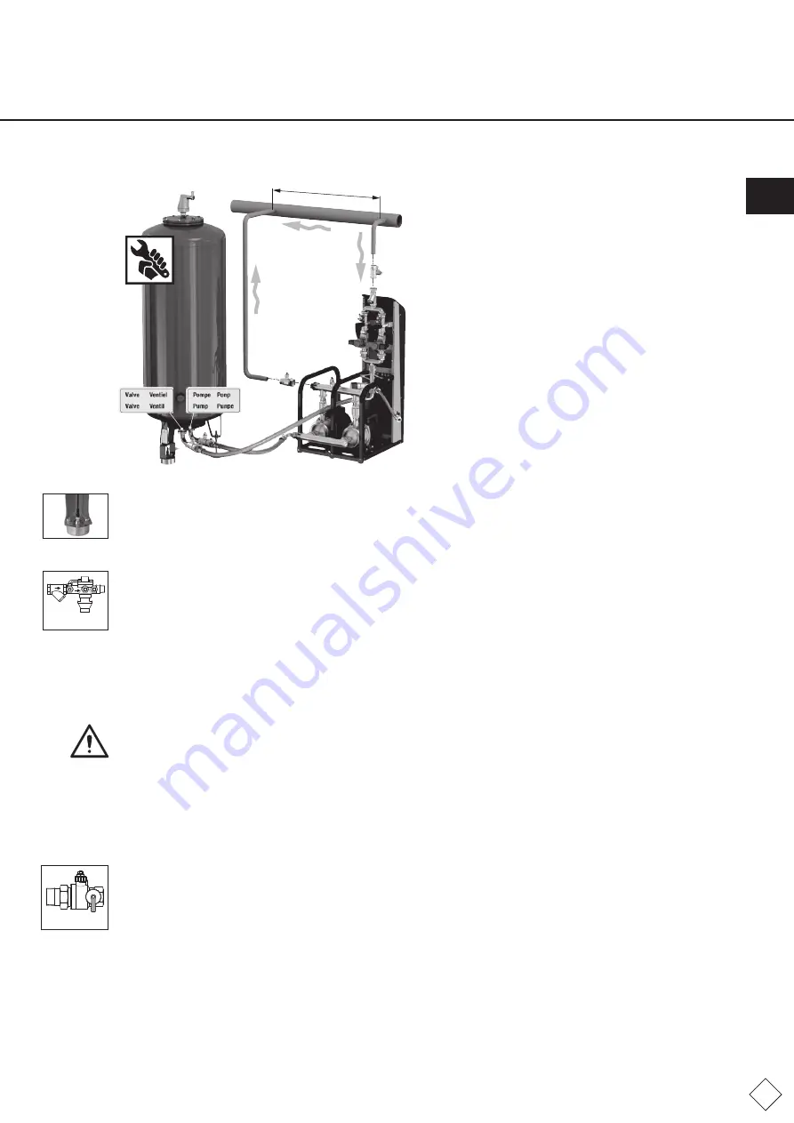
ake note of the labels ‘pump’ and ‘valve’ on the connections and
connect up the appropriate connection from the pump module
(valve) to the pump (valve) on the vessel connection.
Do not cross these connections and, if necessary, mount the
vessel connection flange so as to enable parallel pipe fitting. Use
the flat seals supplied.
•
Connect the signal line via the quick-release connection to the capacity sensor. Screw this connection entirely into the
connector (protection class IP67).
•
Open the lockshield valve on the connection assembly between the vessel (basic vessel, intermediate vessel) and control module.
6.3 Top-up connection
The top-up connection should be connected to the control unit. Assured top-up requires an average set feed pressure of
approx. 4-6 bar (max. 8 bar). High feed pressures may require devices to prevent water hammer (pressure reducing valve).
Appendix 1 shows the installation diagram and example installation.
Please observe the following specifications before filling and commissioning the pressure-expansion automat:
•
Install the feed to the top-up hose with shut-off valve (as delivered).
•
Avoid any tensile loads on the hose, bending radii of less than 50 mm and contractions.
•
If the top-up feed is connected to the water main, a backflow preventer with filter must be connected in series in compliance
with EN 806-4/EN 1717. Install this accessory horizontally and fit a shut-off valve before this assembly (note: clean filter
regularly and change filters as and when required).
Caution:
Connect the shut-off valve to the top-up intake.
6.4 Drain connection
To safely route the volume flows to be discharged at the safety valve (Pos. 3.16), backflow preventer (accessory, top-up) and the
atmospheric pressure compensation connection (Pos.1.3) a drain is required in the vicinity of the Flamcomat equipment.
•
Install a drain funnel and, if necessary, a drain pipe for the backflow preventer.
•
When a discharge pipe is connected to the safety valve, the connection must be kept open to atmospheric pressure. An
atmospheric funnel from the Flamco product catalogue can be fitted for this purpose.
6.5 System connection
The system connection should be connected to the heating or cooling system.
Appendix 1 shows the installation diagram and example installation.
Please observe the following specifications before filling and commissioning the pressure-expansion automat:
•
The connection should preferably be made in the return line of the heating system. Please note that a temperature at the
system connection > 70 °C (...80 °C) would exceed the permissible pump/diaphragm load and possibly lead to damage
to components. (Complete insulation of the expansion pipe may increase the temperature load on the control unit and the
diaphragm).
•
Make sure that this connection is directly connected to the heat generator, and that there are no external hydraulic pressure
influences present at the point of entrainment (e.g. hydraulic balancers, distributors).
•
The flow determines how you should install the expansion lines. When fitting expansion lines to the return > 5 m in length, use
pipes of at least one nominal diameter larger than that of the pump module. Avoid additional loads to the system connection of
the control unit (e.g. from heat expansion, flow oscillations, dead weights).
•
Equipment with flow temperatures > 100 °C must have a minimum pressure limiter fitted in the expansion line (system drain,
valve drain pipework). The arrangement is contained in Appendix 1. In applications in accordance with DIN EN12828:2003 (D),
this limiter is only envisaged for use if the pressure holding device does not have an automatic top-up system.
>1 m - < 2 m
Fig. FM.034.V01.15
Non-return valve
Fig. FM.035.V01.15
Lockshield valve
Fig. FM.036.V01.15
ENG


