


Instruction Manual
D200319X012
377 Trip Valve
August 2012
6
the appropriate flow path C
v
value listed in table 1 for the trip valve. A regulator with insufficient capacity may allow
supply pressure to droop, which can cause the trip valve to trip again and begin a trip‐reset cycle. An example of an
appropriate supply regulator to use with a 377 trip valve is a 64 regulator; its capacity is usually great enough to meet
the demands of most trip valve/actuator combinations. Determine the requirements of your trip valve/actuator
combination for proper selection of a supply regulator.
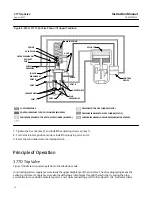
Figure 6. Fisher 2625 Volume Booster used with 377L Trip Valve
2625
1/2 O.D. TUBING
PISTON
ACTUATOR
POSITIONER
3/4 NPT
CHECK VALVE
3/4 NPT OR
1/2 NPT PIPING
SUPPLY
377L
i2P-100/67CFR
3/8 O.D.
TUBING
TYPICAL
NOTES:
1. 3/4 NPT CHECK VALVE AND 1/2 OR 3/4 NPT PIPING ARE REQUIRED.
2. THE SUPPLY PRESSURE REGULATOR SPECIFIED MUST HAVE ADEQUATE CAPACITY FOR 2625 BOOSTERS. ALSO, IF THE 2625 BOOSTER IS TO BE NIPPLE MOUNTED, THE BOOSTER MUST
BE MOUNTED TO A 1/2 NPT OR LARGER CYLINDER CONNECTION. SOME SMALLER CYLINDERS CANNOT BE TAPPED THIS LARGE; CONTACT YOUR EMERSON PROCESS MANAGEMENT
SALES OFFICE FOR AVAILABILITY ON SPECIFIC TYPES AND SIZES.
3/4 NPT OR
1/2 NPT PIPING
21B3153‐B
Note
During normal operation, an adequately sized supply regulator maintains a greater supply pressure than the pressure demand of
the trip valve and control devices. However, if the normal actuator piston position is not relatively close to the actuator piston fail
position during startup, or during the restoration of supply pressure, the regulator supply pressure may droop and cause the trip
valve to trip again and begin a trip‐reset cycle. To prevent this, perform the following steps:
1. Adjust the instrument (control device) pressure to position the actuator piston as it is positioned in the fail mode.
2. Restore the supply pressure to the normal operating range.
3. Manually reset the instrument pressure for normal operation.


