Instruction Manual
D200319X012
377 Trip Valve
August 2012
10
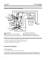
Figure 8. Fisher 377L Trip Valve Shown in Tripped Condition
SPRING
VALVE PLUG
UPPER DIAPHRAGM
EXHAUST
PORT
SUPPLY
PRESSURE
LOWER
DIAPHRAGM
PORT D
PORT E
LOWER PORTS
PORT F
PORT C
PLUG
ASSEMBLIES
UPPER PORTS
PORT B
PORT A
VENT
MAIN SPRING
ACTUATOR
CONTROL
DEVICE
SUPPLY PRESSURE
CONTROL PRESSURE TO TOP OF CYLINDER (BLOCKED)
CONTROL PRESSURE TO TOP BOTTOM OF CYLINDER (BLOCKED)
PRESSURE TO TOP OF CYLINDER (STATIC)
PRESSURE FROM BOTTOM OF CYLINDER (STATIC)
LOWER DIAPHRAGM LOADING PRESSURE (BEING VENTED)
GE08414‐A
A6906-1
7. Tighten the hex nut (key 3), and install the adjusting screw cap (key 1).
8. For the lock‐in‐last‐position mode, reinstall the plugs in ports C and F.
9. Reset the control device for normal operation.
Principle of Operation
377D Trip Valve
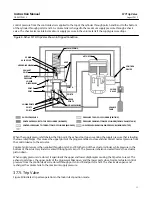
Figure 7 illustrates trip valve operation in the fail‐down mode.
In normal operation, supply pressure loads the upper diaphragm of the trip valve. The valve plug spring keeps the
exhaust port closed. Supply pressure also loads the lower diaphragm through the restriction, causing the plug
assemblies to move down and isolate ports C and F while connecting port A to B and port D to E. Normal actuator


