Instruction Manual
D200319X012
377 Trip Valve
August 2012
11
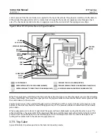
control pressure from the control device is applied to the top of the cylinder through ports A and B and to the bottom
of the cylinder through ports D and E. A volume tank is charged to the maximum supply pressure through a check
valve. The check valve maintains maximum supply pressure in the volume tank if the supply pressure drops.
Figure 9. Fisher 377U Trip Valve Shown in Tripped Condition
SPRING
VALVE PLUG
UPPER DIAPHRAGM
EXHAUST
PORT
SUPPLY
PRESSURE
LOWER
DIAPHRAGM
PORT D
PORT E
LOWER PORTS
PORT F
PORT C
PLUG ASSEMBLIES
UPPER
PORTS
PORT B
PORT A
VENT
MAIN SPRING
ACTUATOR
CONTROL
DEVICE
CHECK
VALVE
VOLUME
TANK
SUPPLY PRESSURE
CONTROL PRESSURE TO TOP OF CYLINDER (BLOCKED)
CONTROL PRESSURE TO TOP BOTTOM OF CYLINDER (BLOCKED)
PRESSURE TO TOP OF CYLINDER (VENTING)
PRESSURE FROM BOTTOM OF CYLINDER (FROM VOLUME TANK)
LOWER DIAPHRAGM LOADING PRESSURE (BEING VENTED)
GE08413‐A
A2284‐6
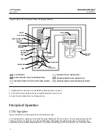
When the supply pressure falls below the trip point, the exhaust port opens venting the supply pressure that is loading
the lower diaphragm. This causes the upper ports of the plug assemblies to close and disconnect normal pressure from
the control device to the actuator.
Volume tank pressure is then applied through ports C and B to the top of the actuator cylinder, while pressure in the
bottom of the actuator cylinder is vented through ports E and F. The pressure imbalance created forces the actuator
piston down.
When supply pressure is restored, it again loads the upper and lower diaphragms causing the trip valve to reset. The
exhaust port closes, the upper ports of the plug assemblies open, and the lower ports close. Normal actuator control
pressure from the control device is restored through ports A and B and ports D and E. The check valve opens and
recharges the volume tank to the maximum supply pressure.
377L Trip Valve
Figure 8 illustrates trip valve operation in the lock‐in‐last‐position mode.


