D-1
APPENDIX D
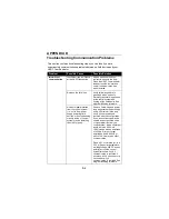
Troubleshooting Communication Problems
This section contains troubleshooting steps you can take if you are
experiencing communications problems between a field device and your
HART Communicator.
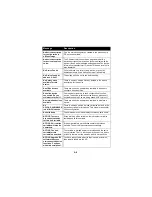
Problem
Possible Cause
Possible Solution
Intermittent
communication
Insufficient loop resistance
at the HART frequencies.
Add an additional 250 ohm
resistor in series in the loop.
Place the HART Communicator
leads across the resistor and
verify if communication has
been restored.
Noise on the field loop
Verify field wiring shield is
grounded at one end only.
Normally, the shield is grounded
at the control system and
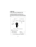
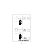
floating at the field device. See
diagram following this table.
Noise or signal distortion
from the control system
(i.e., noise from power
supply powering field
devices or front end analog
circuitry inside of control
system may be distorting
the HART signal).
Remove field wiring and power
loop with external power supply
and a 250 resistor in the loop.
Verify if communication is
restored with this configuration.
If yes, an oscilloscope may be
used to inspect possible noise
or signal distortion from the
control system. Noise of interest
would be in the 800 Hz to
10 KHz range with an amplitude
of 0.5Vpp or larger. Larger
amplitudes below 800 Hz or
above 10 KHz may also affect
communication.
Place a 0.1 microfarad (
µ
f) to a
0.22
µ
f (Capacitor parameters:
working voltage: 50V DC and no
polarity) across the control
system terminals. Verify if
communication is restored. If
not, place a 250 ohm resistor in
series and verify if
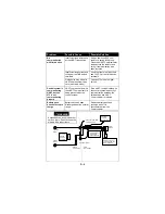
communication is restored. See
diagram following this table.
Summary of Contents for HART 275
Page 48: ...1 40 ...
Page 56: ...2 8 ...
Page 94: ...3 38 ...
Page 106: ...B 6 ...
Page 114: ...D 4 ...

