- 34 -
4.3 Diagnostic
Mode
4.3.1
Entering the Diagnostic Mode
(a) Turn the power supply to the dryer on.
(b) Press and hold the
Auto Dry
down button, then press the
Power
button.
The dryer is now in level 0 of the diagnostic mode. After initial entry into the diagnostic
mode, the
Start/Pause
button operates the dryer as normal. Press the
Auto Dry
up or
down buttons to scroll through the fault levels.
There are several levels of diagnostics, most of which are used in development and
production. These levels may bring on various LEDs, but the level of use for the service
technician is that of the last fault.
4.3.1.1 Last
Fault
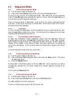
To enter the last fault diagnostics, enter the diagnostic mode as described above, then
press the
Auto Dry
up button three times. The last fault will be displayed on the drying
progress LEDs as described in Section 4.1.
4.3.1.2
Conductivity Contact Impedance
To enter the conductivity contact impedance check, enter the diagnostic mode as
described above, then press the
Auto Dry
up button five times. In this mode, touching
damp clothes or fingers across the conductivity contacts will cause the LED display to
change. If the contacts, or the harness to them, have gone open circuit, no change will
occur in the LED display. This is a useful method of checking the integrity of the sensor
circuits.
To exit the diagnostic mode, press any cycle button.
4.3.2
Entering the Data Download Mode
(a) Turn the power supply to the dryer on.
(b) Press and hold the
Auto Dry
down button, then press the
Power
button. This enters
the diagnostic mode.
(c) Press
the
Regular
button.
Encoded data is transmitted serially out the red
Auto
LED, and is captured by an optical
download pen attached to a PC where “Smart Tool” software interprets the data to aid
servicing.
To exit, press the
Regular
button.
4.3.3
Entering the Showroom Mode
(a) Turn the power supply to the dryer on.
(b) Press and hold the
Air Dry
button, then press the
Power
button.
The LEDs will flash in a random sequence.
To exit, turn off the power supply to the dryer at the wall.
Summary of Contents for Smartload DEGX1
Page 1: ...DRYER Models DEGX1 DGGX1 517760 ...
Page 2: ......
Page 60: ... 60 7 Wiring Diagrams 7 1 U S A Model Electric ...
Page 61: ... 61 7 2 U S A Model Gas ...
Page 69: ... 69 Notes ...

