- 57 -
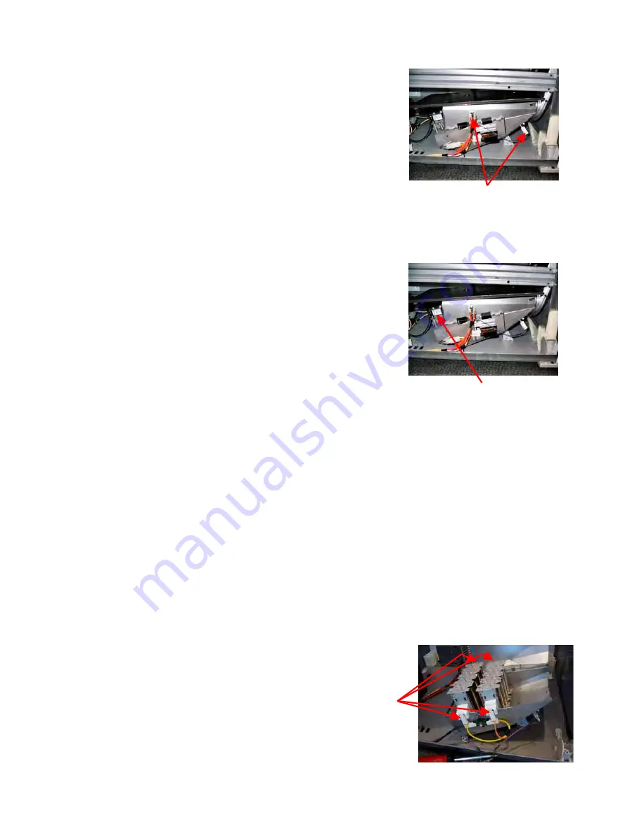
6.39 Removal of Thermostats
(a) Follow general servicing instructions for
components within the cabinet. (Refer to Section
6.6)
(b) Remove the push on connectors from the
appropriate thermostat terminal.
(c) Remove the screw securing the thermostat to the
combustion housing and lift the thermostat clear.
Reassembly
(a) Refit in reverse manner.
6.40 Removal of Gas Regulator Valve, Pipe and
Burner Tube (Gas Models)
(a) Disconnect the dryer from the gas supply.
(b) Follow instructions for removal of the drum and
chassis assembly. (Refer to Section 6.16)
(c) Remove the push on connectors from the
thermostat attached to the top combustion housing.
(d) Remove the screw securing the top combustion
housing to the bottom combustion housing, hinge
up and lift clear.
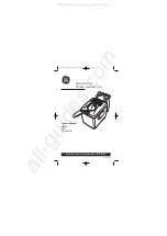
(e) Remove the push on connectors from the gas
regulator valve.
(f)
Remove the screw securing the gas igniter bracket and lift the bracket clear.
(g) Slide the gas burner bracket to the left and lift clear of the slots in the base panel. Lift
the gas regulator valve and pipe assembly forward and out.
(h) Remove the two screws securing the gas burner venturi.
(i)
Remove the three screws securing the gas regulator valve to the bracket.
(j)
Unscrew the gas pipe from the gas regulator valve.
Reassembly
(a) Refit in reverse manner. Ensure that the regulator/valve is screwed onto the gas
pipe to the correct angle so that the gas burner bracket sits flat on the base panel
when assembled. Ensure that the gas pipe bracket tabs go through the slots in the
back of the base panel.
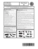
6.41 Removal of Elements (Electric Models)
(a) Follow instructions for removal of the drum and chassis assembly. (Refer to Section
6.16)
(b) Remove the push on connectors from the thermostat attached to the top combustion
housing.
(c) Remove the screw securing the top element housing
to the bottom element housing.
(d) Lift the top housing clear.
(e) Remove the push on connectors from the
element.
(f)
Lift the element clear.
Reassembly
(a) Refit in reverse manner.
Thermostats
Gas regulator valve
Summary of Contents for Smartload DEGX1
Page 1: ...DRYER Models DEGX1 DGGX1 517760 ...
Page 2: ......
Page 60: ... 60 7 Wiring Diagrams 7 1 U S A Model Electric ...
Page 61: ... 61 7 2 U S A Model Gas ...
Page 69: ... 69 Notes ...


