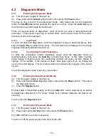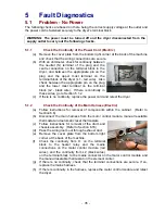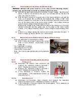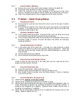
- 36 -
5.1.3
Check the Continuity of the Power Cord (Gas)
(a) Follow instructions for removal of the drum and chassis assembly. (Refer to
Section 6.16)
(b) Pass the main power cord through the exhaust
duct.
(c) Disconnect the 3 way in-line connector that is
clipped to the motor controller.
(d)
With an ohmmeter, check for continuity between
the neutral (N) terminal of the plug and the
outside connection on the in-line plug in the
dryer (white wire), and between the line/phase
pin on the plug and the centre connection on the
terminal block of the dryer (black wire).
(d) If there is no continuity, replace the power cord and retest the dryer. If there is
continuity, go to Section 5.1.4.
5.1.4
Check the Continuity of the Main Harness (Gas)
(a) Follow instructions for removal of the drum and chassis assembly. (Refer to
Section 6.16)
(b) Disconnect the in-line connector that is clipped to the motor controller.
(c)
Check the continuity from the centre terminal on the in-line plug to the mains
connector on the motor control module (red wire), and from the outside terminal
on the in-line plug to the mains connector on the motor control module and the
gas valve (white wires).
(d)
If there is continuity, replace the motor control module and retest the dryer.
(e)
If there is no continuity, replace the mains harness and retest the dryer.
5.2
Problem - No Heat
5.2.1
Check All Thermostats (Gas and Electric)
WARNING: The power must be disconnected to perform the following checks.
(a)
Check that the manual reset thermostat has not tripped. If it has, reset it.
(b)
Disconnect each thermostat one by one and check the continuity of each.
(c)
If any of the thermostats have no continuity, replace the offending thermostat. If
all thermostats have continuity, go to Section 5.2.2 (electric) or 5.2.5 (gas).
5.2.2
Check the Elements (Electric Only)
(a) Follow instructions for removal of components within the cabinet. (Refer to
Section 6.6)
(b) With an ohmmeter, measure the resistance across both elements.
(i) Measure the resistance of the 1.4kw element between the violet wire on the
front element connection and the violet wire on the mains relay on the motor
control module. The cold resistance should be between 38 and 45 ohms.
(ii) Measure the resistance of the 3.6kw element between the yellow wire on
the front element connection and the yellow wire on the relay on the motor
control module. The cold resistance should be between 13 and 19 ohms.
(c)
If there is an open circuit replace the element, otherwise go to Section 5.2.3.
Summary of Contents for Smartload DEGX1
Page 1: ...DRYER Models DEGX1 DGGX1 517760 ...
Page 2: ......
Page 60: ... 60 7 Wiring Diagrams 7 1 U S A Model Electric ...
Page 61: ... 61 7 2 U S A Model Gas ...
Page 69: ... 69 Notes ...


