


- 49 -
6.18 Removal of Outlet Duct Assembly
(a) Follow instructions for removal of the outlet panel
assembly. (Refer to Section 6.17)
(b) Remove the wiring loom plugs from the sensor
module assembly.
(c) Remove the sensor module assembly from the outlet
chassis panel. (Refer to Section 6.36)
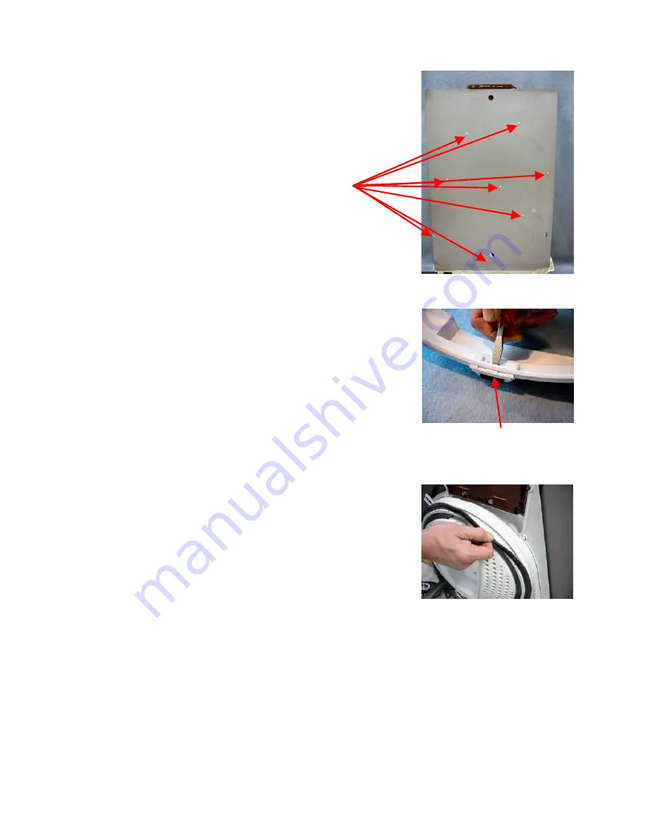
(d) Lay the outlet panel assembly down with
the outlet chassis panel uppermost.
(e) Remove the eight screws from the panel.
(f)
Lift the panel clear of the duct assembly.
Reassembly
(a) Refit in reverse manner.
6.19 Removal of Outlet Duct Bearings
(a) Follow instructions for removal of the outlet panel
assembly. (Refer to Section 6.17)
(b) Lift the collector housing bracket clear of the outlet
duct assembly.
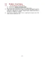
(c) With a screwdriver, push the tab on the back of the
bearing assembly to push it out of the outlet duct
assembly.
Reassembly
(a) Refit in reverse manner.
6.20 Removal of Outlet Duct Seal
(a) Follow instructions for removal of the outlet duct
assembly. (Refer to Section 6.18)
(b) Remove the outlet duct bearings. (Refer to Section
6.19
(c) Grasp the seal and pull it out of the groove in the
outlet duct assembly, being careful not to tear the
seal away from the plastic strip that it is welded to.
Reassembly
(a) Refit in reverse manner.
Bearing assembly
Summary of Contents for Smartload DEGX1
Page 1: ...DRYER Models DEGX1 DGGX1 517760 ...
Page 2: ......
Page 60: ... 60 7 Wiring Diagrams 7 1 U S A Model Electric ...
Page 61: ... 61 7 2 U S A Model Gas ...
Page 69: ... 69 Notes ...