


DFLEX Assembly instructions |
43
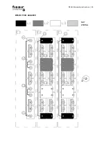
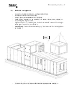
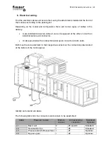
5.7
Module 6 arrangement
-
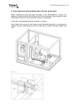
Locate the module identified as -6- (Reactivation Filter).
-
Remove the protections for transport.
-
Hang it by the locks installed for this purpose.
-
Place it over module -3-, at a distance of about 100mm from module -5-,
maintaining the alignment axis.
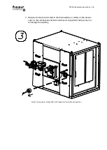
-
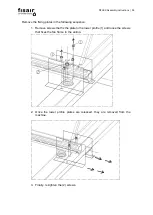
Approach module -5-, matching the section marked S6-5, and screw the flanges
of the gate of module -5- to module -6-.
-
IMPORTANT: These screws are for fixing only, the module -6- must be supported
by module -3-.
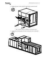
-
Once secured, you can remove the tubes that supported the module -5-.
S6-5
Summary of Contents for DFLEX 1100
Page 2: ...DFLEX Assembly instructions 2...
Page 16: ...DFLEX Assembly instructions 16 The following result is obtained...
Page 29: ...DFLEX Assembly instructions 29 DFLEX 1100 400V 5...
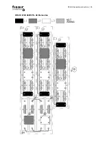
Page 30: ...DFLEX Assembly instructions 30 DFLEX 1100 440 480V NOT WIRING...
Page 31: ...DFLEX Assembly instructions 31 DFLEX 1300 400V 5...
Page 32: ...DFLEX Assembly instructions 32 DFLEX 1300 460V 5 NOT WIRING...
Page 33: ...DFLEX Assembly instructions 33 DFLEX 1700 400V 5...
Page 34: ...DFLEX Assembly instructions 34 DFLEX 2100 400V 5...
Page 35: ...DFLEX Assembly instructions 35 DFLEX 2100 460V 5 48 Elementos NOT WIRING...
Page 36: ...DFLEX Assembly instructions 36 DFLEX 2100 460V 5 45 elements Requires SSR in E4 NOT WIRING...


