


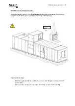


DFLEX Assembly instructions |
17
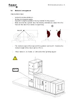
5.5
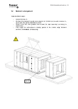
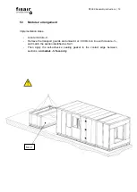
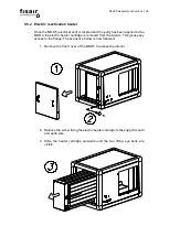
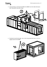
Module 1 arrangement
Implementation steps:
-
Now locate and unpack module -1-. Apply the self-adhesive sealing gasket to the
contact edge of sections S1-4 and S1-2
on the face of the module only
.
-
Unload the module at> 100 mm from the previous module, centered and aligned
with the longitudinal axis by matching the section identified as S1-2.
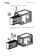
-
Once the module, -1-, has been placed on the platform, move it longitudinally
until it makes contact with the adjacent section.
-
When the module -1 is in position, place the screws of the connecting sections
between the modules -1-, -2- and -4-.
REMEMBER
: The bolts should not exert
traction. Make sure that the modules -1-, -2- and -4- are perfectly aligned and
there is no gap between the two.
Do not apply final tightening yet
.
S1-4
S1-2
Summary of Contents for DFLEX 1100
Page 2: ...DFLEX Assembly instructions 2...
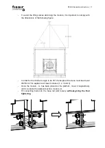
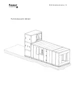
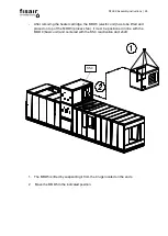
Page 16: ...DFLEX Assembly instructions 16 The following result is obtained...
Page 29: ...DFLEX Assembly instructions 29 DFLEX 1100 400V 5...
Page 30: ...DFLEX Assembly instructions 30 DFLEX 1100 440 480V NOT WIRING...
Page 31: ...DFLEX Assembly instructions 31 DFLEX 1300 400V 5...
Page 32: ...DFLEX Assembly instructions 32 DFLEX 1300 460V 5 NOT WIRING...
Page 33: ...DFLEX Assembly instructions 33 DFLEX 1700 400V 5...
Page 34: ...DFLEX Assembly instructions 34 DFLEX 2100 400V 5...
Page 35: ...DFLEX Assembly instructions 35 DFLEX 2100 460V 5 48 Elementos NOT WIRING...
Page 36: ...DFLEX Assembly instructions 36 DFLEX 2100 460V 5 45 elements Requires SSR in E4 NOT WIRING...


