


DFLEX Assembly instructions |
26
-
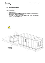
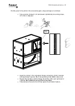
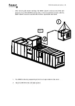
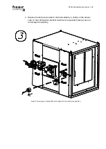
After removing the heater cartridge, the MOD5 (electric unit) has to be lifted and
placed on top of the MOD3 (process fan). It must be positioned in line with the
MOD4 (basic unit) and centered with the S5-4 reactivation duct shaft:
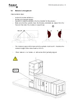
1. The MOD5 is lifted by suspending it from the 4 lugs located on the ends.
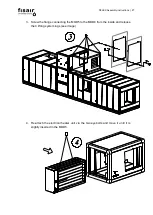
2. Move the MOD5 to the indicated position.
S5-4
Summary of Contents for DFLEX 1100
Page 2: ...DFLEX Assembly instructions 2...
Page 16: ...DFLEX Assembly instructions 16 The following result is obtained...
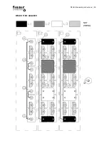
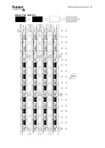
Page 29: ...DFLEX Assembly instructions 29 DFLEX 1100 400V 5...
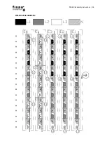
Page 30: ...DFLEX Assembly instructions 30 DFLEX 1100 440 480V NOT WIRING...
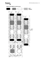
Page 31: ...DFLEX Assembly instructions 31 DFLEX 1300 400V 5...
Page 32: ...DFLEX Assembly instructions 32 DFLEX 1300 460V 5 NOT WIRING...
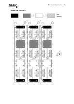
Page 33: ...DFLEX Assembly instructions 33 DFLEX 1700 400V 5...
Page 34: ...DFLEX Assembly instructions 34 DFLEX 2100 400V 5...
Page 35: ...DFLEX Assembly instructions 35 DFLEX 2100 460V 5 48 Elementos NOT WIRING...
Page 36: ...DFLEX Assembly instructions 36 DFLEX 2100 460V 5 45 elements Requires SSR in E4 NOT WIRING...


