2
© 2021 Carrier
2.
OPERATION PRINCIPLE AND TECHNICAL
SPECIFICATION
Unit construction provides a stable flame, ignition repeatability, low demand for combustion and cooling air. No
moving parts ensure long, trouble-free operation with low maintenance costs.
SureFire IITM
Pilot SP-32-NG/PG-FD
can operate as an intermittent (light-off), or as a continuous pilot.
Main parts of
SP-32-FD
pilot are: air tube (pos. 4 on Fig. 1) with combustion-cooling air inlet (3/4”BSP) and gas part
assembly including gas head (pos. 3) with gas inlet (1/2” BSP) and ignition rod hole (1/2”BSP) with igniter rod holding
gland (pos. 6) together with the fixed gas tube (pos. 2). The orifice-stabilizer assembly (pos. 1) is fixed at the end of gas
tube. Orifice-stabilizer assembly consists of nipple with main and bleeding orifices, mounting bracket and stabilizer.
Gas part assembly is mounted in the air tube by means of the thread joint with mounting ring (pos. 5).
Note that gas supply line should be equipped with an effective strainer unit to prevent the orifices from clogging.
In many applications
SP-32
pilots are mounted on the main burner using the mounting tube (see p.3).
The source of ignition is an electrical high energy spark igniter (HESI) or high tension arc igniter (HTI) for safe or
hazardous area (depending on the application) equipped with the ignition rods of outer diameter of 16 mm and coaxial
electrode arrangement.
The ignition rod is mounted in the gas head and goes through air tube to the mounting bracket of the orifice-stabilizer
assembly. The rod tip end should be placed as on drawing Fig. 1 (depending on the kind of ignition device), to provide
a successful ignition of air-gas mixture.
Gas pilot
SP-32-FD
can be supplied together with electrical ignition device selected depending on the application.
Ignition device is not in gas pilot scope of supply and should be ordered separately.
SP-32-FD
pilot principle of use: gas is supplied through the inlet 1/2“BSP to the gas head and to the gas tube and
orifice-stabilizer assembly. Gas exits the main nozzle to the primary combustion zone. At the same time a small
amount of gas leaves through the bleed orifice before the stabilizer plate, passing into the zone where it mixes with
air to form a combustible mixture. The orifice-stabilizer assembly is optimized for Natural gas or Propane gas/LPG.
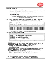
In case of other Fuel gas type or other capacity needed, contact Fireye as this may need the pilot construction changes
- see p. 11 for Special Pilots.
Ignition is initiated by a spark or an electric arc generated at the tip of the electrical igniter rod in zone before stabilizer.
The pilot flame stabilizes at stabilizer plate while main flame stabilizes in the primary combustion zone, at the outlet
of the air tube. Thanks to this principle of design, the pilot combustion zone is protected, the main combustion zone
is outside the pilot, and hence the air tube does not overheat and there is no need for retraction of the ignition device
rod.
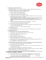
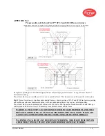
Pilot has to be mounted on main burner such that no part of pilot shall be in the main burner flame and cannot project
beyond the heater lining or a burner throat. The distance of the tip of pilot air tube from the main burner flame should
not be smaller than 150 mm
–
see Appendix 2.
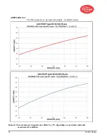
The flame length is 0.4 – 0.6 m depending on the kind of gas, air and gas pressures versus the pressure in combustion
chamber.
In addition, using Fireye high tension igniter type
HTSS
in the
Spark & Sense
version, the center electrode of igniter
rod is also an ionization rod extended into the primary combustion zone and specially designed to work with
SureFire
IITM
Pilots. The HT igniter creates the electric arc to ignite the gas, and then the electric circuit switches the operating
mode for ionization detection, confirming the presence of the igniter flame.
FIGURE 2.
Pilot mounting tubes: for welding and flanged

