background image

Firetide - Reliable Connectivity Anywhere

 7


February 2009 

Chapter 3  Setting Up Your Equipment - Model 4200 Outdoor Installation

Setup - Outdoor Model 4200

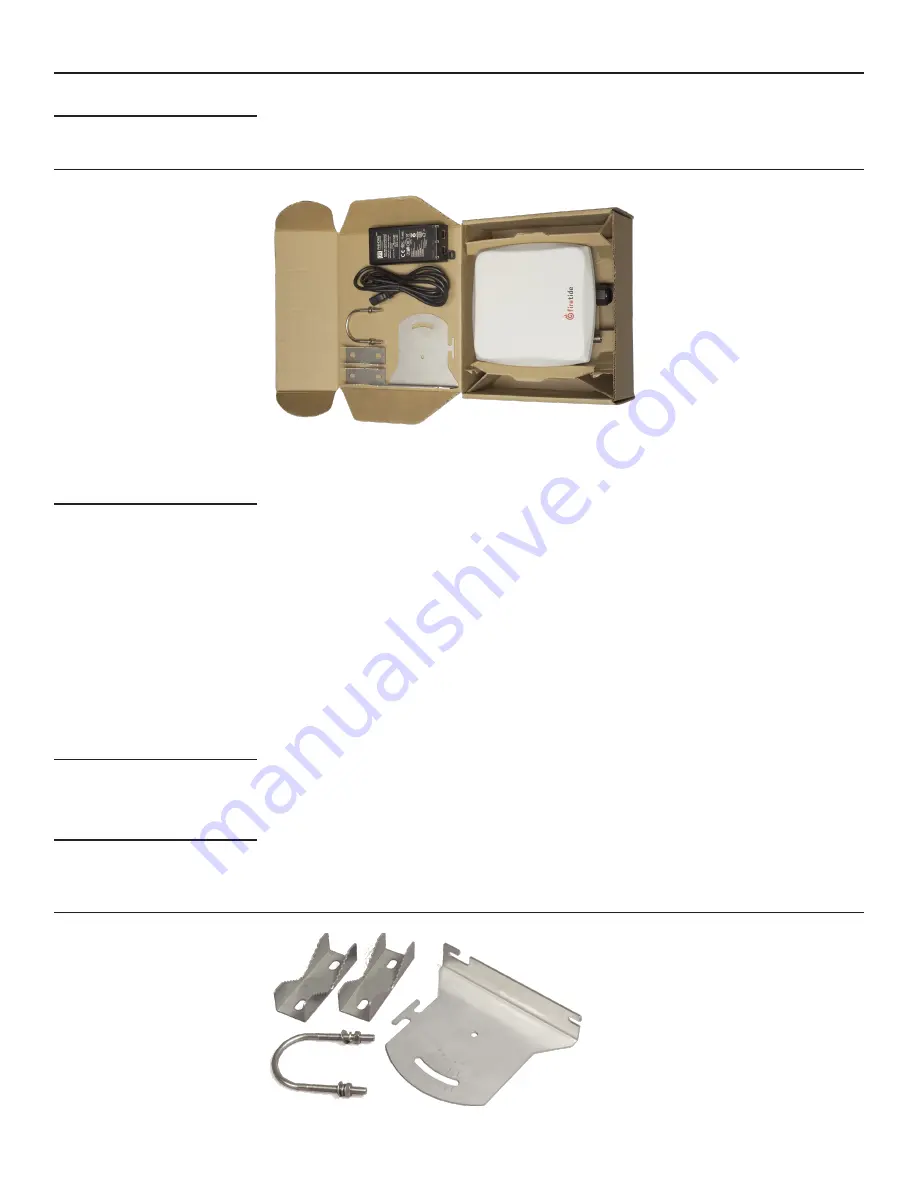
  The outdoor HotPoint is packed as shown in Figure 3. Note that an Ethernet cable is NOT included. 

You should obtain a weatherproof 4-pair cat-5 cable long enough to reach from the unit to the 
indoor location where you will connect with the network. Configure your HotPoint before installa-
tion. Refer to Chapter 6, or the HotView Pro Reference Guide, for details.

Figure 3. Model 4200 Outdoor Unit - Package Contents


The cable must be a 4-pair cable; smaller cables will not seal in the waterproof connector. The 
cable can be pre-terminated; the waterproof connector will pass an RJ-45 plug.

Assembling the Ethernet Cable

  Test the unit before mounting it on the pole or mast. Begin by making the cable.

Remove the weatherproof Ethernet connector cover - the black plug - from the unit.

1. 

Dismantle it. You will have a housing, a housing insert, a cap, and a gasket.

2. 

Place the cap over one end of your Ethernet cable.

3. 

Place the housing insert over the cable.

4. 

Thread the cable through the housing.

5. 

Plug the cable into the RJ-45 port visible inside the HotPoint.

6. 

Thread the housing back into the HotPoint. Make sure the gasket is still in place.

7. 

Tighten the cap so that it compresses the housing insert to the housing.

8. 


Now you can connect the Ethernet cable to the power feed unit, via the OUT port on the power 
feed unit. Use a second Ethernet cable to connect the IN port to your PC. Verify operation of the 
HotPoint before proceeding.

Using the Mounting Bracket

  The bracket is designed to allow easy tilting and aiming of the HotPoint. The bracket allows the 

HotPoint to be mounted with its internal antenna oriented for either vertical or horizontal polar-
ization. It is also designed to allow mounting on either a horizontal or vertical pole. Note that the 
internal antenna polarization is vertical when the connectors are pointed down.

Antenna Notes

  Note that the antenna is built in to the HotPoint. The HotPoint should face the equipment it is 

intended to connect with. The built-in antenna is designed for the 2.4 GHz band, that is, 802.11b 
and 802.11g service. The HotPoint 4200 supports operation on the 5 GHz 802.11a band, but you 
must use an external 5 GHz antenna if you wish to use this band. Otherwise, keep the plastic cover 
on this connected to prevent water from getting into the unit.

Figure 4. HotPoint Mounting Bracket

Summary of Contents for HotPoint 4100

Page 1: ...notice Please refer to the Firetide partners web site partners firetide com for current versions Installation Setup Guide HotPoint 4000 Family Wireless Access Points HotPoint 4600 Outdoor Access Poin...

Page 2: ...and anticipate possible hazards Never assume anything without checking it out for yourself Don t take shortcuts TO AVOID FALLING USE SAFE PROCEDURES WHEN WORKING AT HEIGHTS ABOVE GROUND Select equipm...

Page 3: ...ption loss of information or other pecuniary loss arising out of the use or inability to use the product or the performance interruption or failure of the product irrespective of the cause of action e...

Page 4: ...erat ing on a different channel a video camera a VoIP device or even a third party access point Firetide HotPort Mesh Network Firetide s wireless mesh technology provides an ideal backhaul capability...

Page 5: ...GHz band 5 0 GHz band 802 11d 802 11b g 802 11a Turbo mode for supported clients WMM QoS WDS server WDS client Security Features Rogue AP Detection 802 11i 40 128 WEP 128 256 AES TKIP WPA WPA2 encryp...

Page 6: ...to 240 VAC from 50 to 60 Hz If you need PoE capability use the 4200 Figure 1 Model 4100 Indoor Unit Package Contents The 4100 needs to connect via a standard Ethernet RJ 45 cable to the network Pick a...

Page 7: ...lug the cable into the RJ 45 port visible inside the HotPoint 6 Thread the housing back into the HotPoint Make sure the gasket is still in place 7 Tighten the cap so that it compresses the housing ins...

Page 8: ...er poles by placing it over the U bolt before putting the U bolt around the pole After placing the U bolt around the pole place the bracket over the legs of the U bolt such that one leg passes through...

Page 9: ...tallation Refer to Chapter 6 or the HotView Pro Reference Guide for details Your AP includes a power supply and three different AC line cords as shown in Figure 9 Use the one appropriate for your regi...

Page 10: ...r clamp of Figure 11 The purpose of the spacer nuts is to prevent the U bolt legs from protruding too far out beyond the plate This will interfere with the AP If required place two more spacer nuts on...

Page 11: ...iew of all HotPoints or information on statistics and performance HotView and HotView Pro do for details on their use refer to the HotView Pro Reference Guide Note that HotPoint capabilities are the s...

Page 12: ...word AP AP AP VAP VAP VAP Figure 16 shows a three AP three VAP configuration You can have multiple VAPs per physical AP Figure 16 Large AP Matrix Name IP Address Firewall VPN Name IP Address Firewall...

Page 13: ...CP available 192 168 224 160 Log in to the AP 3 Set the Country Code 4 Change the default password 5 Rename the AP A name based on the AP s location is a good choice 6 Set the radio settings channel e...

Page 14: ...e available Virtual APs If the AP is new no VAPs will be shown if the unit has already been placed into service you will see a list of existing VAPs as in this case Model 4100 4200 and Model 4500 4600...

Page 15: ...her SSID pa rameters Note that the maximum power level will be less that 26 dBm 400 mW if you are on a channel where reduced power is required or if you have reduced power on the main radio settings p...

Page 16: ...nd parameters from the available choices Screen 4 VAP Security Settings Network Settings Each VAP has its own network settings as shown in Screen 5 A VAP has a unique IP address it is this address tha...

Page 17: ...clients on the same AP from seeing each other This provides ad ditional security especially for public hotspots WMM provides QoS support for multimedia applications VLANs provide a method of isolating...

Page 18: ...AP and remotely restore it to factory default settings Keep in mind that resetting to factory defaults will change the IP address to 192 168 224 160 You may need to modify your computer settings to r...

Page 19: ...mW max Bands GHz Frequency GHz Restrictions 802 11a 4100 4200 5 15 5 25 5 25 5 35 5 725 5 825 4 9 5 090 4 94 4 990 Japan only US Public Safety 5 470 5 725 ETSI 301 893 U NII 802 11b g all models 2 412...

Page 20: ...to 90 Storage humidity non condensing 5 to 95 Maximum altitude 15 000 feet 4600 meters Model 4500 Indoor Unit Specifications Enclosure Plenum rated per UL2043 System indicator LEDs power uplink access...

Page 21: ...emperature 40 C to 60 C Storage temperature 40 C to 70 C Humidity non condensing 10 to 90 Storage humidity non condensing 5 to 95 Maximum altitude 15 000 feet 4600 meters Model 4600 Outdoor Unit Speci...

Page 22: ...hat to which the receiver is connected Consult the dealer or an experienced radio TV technician for help FCC Radiation Exposure To ensure compliance with the FCC s RF exposure limits the antenna used...

Page 23: ...5 VDC to 48 VDC 6 RXD RX Data 10 BaseT 100BaseTX 7 PoE Power Input 5 VDC to 48 VDC 8 PoE Power Input 5 VDC to 48 VDC Appendix D Reset Procedure Firetide Access Points may be reset to factory parameter...

Page 24: ...2 USA Copyright Notice 2009 Firetide Inc All rights reserved Trademarks Firetide the Firetide logo Instant Mesh Net works HotPort HotPoint and HotClient are trademarks of Firetide Inc All other tradem...

Reviews: