


6
CoMMIssIonIng
Note: When fine tuning the burner with the flue
gas analyser, adjustments in both the air and pump
pressure may be required to achieve the desired
CO
2
%.
u
Print off a copy of the flue analysis and attach to the
commissioning card.
u
Make sure the flue gas analysis plug is replaced
correctly into the flue when finished the flue analysis.
u
Check the correct operation of the thermostat on the
boiler.
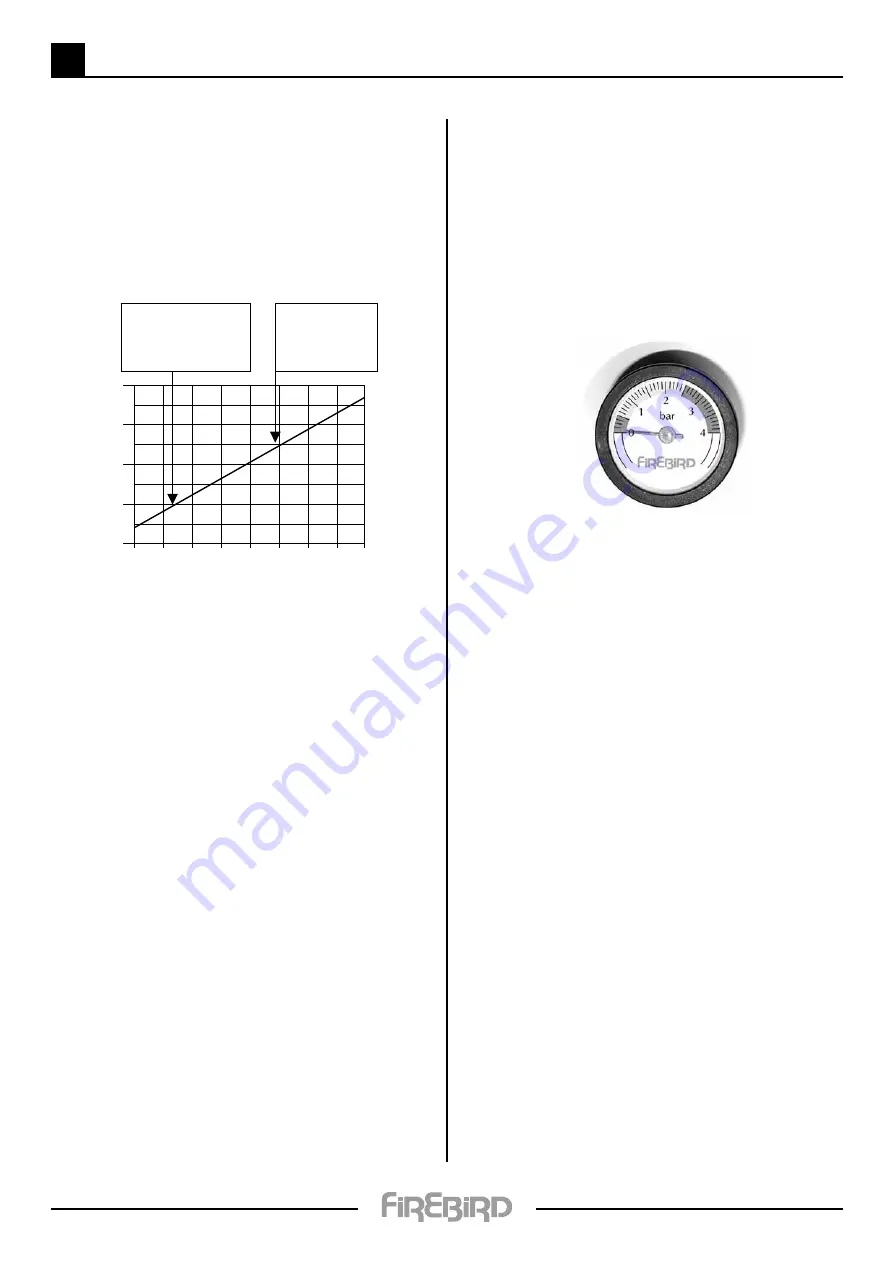
1% rise in CO
2
as the ambient
temperature rises
by 20°.
In the cold of winter
aim for lower CO
2
%.
In warmer times of the
year set the CO
2
higher.
0
5
10
15
20
25
30
35
40
12
12.5
13
11
11.5
Outside air temperature (˚C)
%
CO
2
CoMMIssIonIng
Before proceeding to filling, ensure that electricity
supply is switched off at mains to avoid any possibility
of time switch operating and passing power to
appliance prior to filling.
Filling and testing
Check that all connections, especially compression joints,
are fully tightened. Re-check and ensure that the pressure
vessel air charge is correct, then fill the system with water
via the filling system used. turn off the water supply
before system pressure reaches safety valve operation
point of 3 bar (2 to 2.5 bar). Vent system via all manual
air vents including circulating pumps, boiler, radiators,
system high points. etc. Check that dust caps are loosened
on auto air vents, keep constant check on system pressure
gauge (fitted to control panel). If pressure has dropped
re-admit water to above pressure. ensure all appropriate
boiler and system valves are open.
With the water supply turned off, thoroughly flush out
the boiler and system to remove all foreign matter before
allowing the boiler and pumps to operate. If in doubt,
drain the system and repeat above procedure. at this
stage flushing-out water should be clean and clear of all
foreign matter.
Refill the system and again vent at all points as described.
examine the complete system for water leaks having
pressurised it to 1 - 2.5 bar. Correct any leaks, then check
operation of the safety valve by admitting further water
until this valve operates. This should occur when system
pressure rises to between 2.7 and 3.3 bar. When satisfied
with valve operation, and with mains water still turned
off, draw off sufficient water until initial system design
fill pressure (P
i
). (cold fill) is established (0.5 - 1 bar - as
calculated for system).
Remember that initial cold fill pressure can only be
checked when system water has properly cooled down.
Check that the final operating pressure (P
f
) is under 2.5
bar with all radiators turned on and up to the highest
working temperature. Should system operating pressure
exceed this, check:
1.
That initial cold fill pressure is correct and ,
if additional expansion vessel is fitted, that
pressure is equal in each vessel.
2.
That expansion vessels are sized correctly.
special attention should be given to existing heating
systems where a Firebird boiler has replaced an
existing unit. extra effort should be made to ensure
that all original pipe work and radiators are repeatedly
flushed. If possible use a proprietary cleansing agent
suitable for the system as loosened scale and foreign
matter can seriously reduce domestic hot water
performance and pump efficiency.
use corrosion inhibitor of suitable type.
HandIng over
The end user should receive:
• A clear and concise demonstration of the boiler
operation and any system controls.
• This manual, the burner manufacturer’s manual
and any other instructions.
• OFTEC forms CD10 and CD11.
The end user should be advised to:
• Service the boiler annually and to ensure that the
service records are completed.
• Read the terms and conditions of warranty.
• Keep all boiler documentation in a safe place.
a commissioning record should be completed
and a copy retained by the engineer.
33